Modbus conversion Micrologix 1100 to Contrologix Prosoft MVI56

abdriver

Member
Join Date
Feb 2010
Location
Lille
Posts
7
Hi gents,

i'd like to know what are the guidelines for converting a Micrologix 1100 program to a Contrologix in term of modbus communication.

this micrologix 1100( mainly used as concentrator) is comunicating with a Yokogawa DCS throught Modbus (Channel 0 )

the target is to replace it with a contrologix (and Prosoft MVI56) without any modification from DCS side.

i know there are some prosoft sample codes ,but how can i adapt it for the exising system.

tanks for your time .
 
the setup for modbus on those two is completely different. on the micrologix you just tell it what data file will be used as the modbus function. setting up the mvi56 is pretty easy also. basically they give you the code, then I believe you have to set up some arrays if I remember correctly then map your data to the arrays. its not hard, but can be more complicated than the micrologix modbus setup of course. the great thing is that prosoft support is excellent. rest assured that they will help you solve any problem quickly.
 
There will be a little more work to configure the modbus in ControlLogix using the Prosoft (MVI56-MCM?), but the example code provided with the Prosoft module will have most of the work done for you. The manuals for the modules are a little tough to navigate if you have never worked with a Prosoft before, but they can be quite helpful as well.

I believe the arrays that diat150 is talking about are created when you add the Prosoft module into the ControlLogix I/O. By default there are two arrays, 600 [INT] for READ_DATA and 600 [INT] for WRITE_DATA. Through logic you can map in the data to be read by or written to the DCS, and it should be easy to lay it out in the same order that it is in the ML1100, allowing the DCS side to remain the same.

Prosoft does offer good technical support that should be able to help you work through any issues you may have.
 
Modbus with Prosoft card is very easy with their very good support. You should get advices directly by chatting with Prosoft'support team.
 
If you haven't already bought the Prosoft device, you could also use a Red Lion datastation. They list out at about $600, and will not only do the modbus to PCCC translation easily, but you will also have more ports available when you are done to add devices / expand in the future.
 
If you haven't already bought the Prosoft device, you could also use a Red Lion datastation. They list out at about $600, and will not only do the modbus to PCCC translation easily, but you will also have more ports available when you are done to add devices / expand in the future.

you could do the same with a digi one iap for cheaper. I think the mvi56 would be easier than either of these options.
 
Thank you for your very usefull replies , i ll work on it and let it you know about it ....
I got another question , do u know if ACL instruction can be used on a micrologix 1100 to clear the comm buffer ( channnel 0 used as Modbus RTU Master ).to work around modbus comm locking up .
the reason i'm thinking it could help is the fact that when it happens we only power cycle and it works again.:unsure:
 
No, the ASCII buffer instructions only work when the port is in ASCII mode.

99% of the "comms locking up" problems I have seen are because of the way MSG instructions are written in the controller. If you can post your MicroLogix program, then Forum members may be able to help you analyze it.

Are you migrating from MicroLogix 1100 to ControlLogix with Prosoft because of this "locking up" issue, or for another reason ?
 
Hi Ken ,
thansk for your reply .

1/please find here attached two program example .
micrologix is communicating with 7 or 6 N-DIN (protection relays) MG9:0 LADDER 20


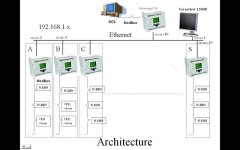
2/ the reason we're migrating is mainly because of comm lockupon the Concentrator 192.168.1.40 from DCS side,but when we investigate the program we've find the problem is on another side( between each micrologix and Modbus).
HERE ATTACHED THE ARCHITECTURE

thanks again for your usual support

Architecture.jpg
 

Attachments

  • Folder.zip
    75.8 KB · Views: 54
Hi ken ,
another thing the reason i was thinking it could work is this TIP i've read in page 315 Instruction Set Reference
Manual Publication 1763-RM001C-EN-P - October 2009

For MicroLogix 1100, the ACL instruction can also be
used to clear the DF1 communication buffers when the
channel is configured for any of the DF1 communication
drivers.
Select 0 for the channel number that is configured for
DF1 and Yes for both the Receive and Transmit Buffers.
When the ACL instruction is executed, any pending
outgoing DF1 replies, any pending incoming DF1
commands and any pending outgoing DF1 commands
are flushed. Any MSG instructions in progress on that
channel will error out with an error code of 0x0C.
However, this functionality is not applied if DCOMM

(Default communication setting) is selected.
 
I stand corrected; I did not know that the ACL instruction would clear the DF1 buffers in a MicroLogix 1100 controller. Thank you for posting that !

I do not believe that it does the same thing in the SLC-5/0x modular controllers. But now that you have pointed out a relatively recent publication, I will have to check carefully or test to be certain.

That manual is fairly specific about DF1 mode, so I would guess that it does not do the same thing in Modbus RTU mode, but again I would have to try to figure that out by testing before I posted about it.

I will have a look at your architecture drawing later in the day.
 
It's very good that you were able to post the architecture diagram, but these programs have a few things going against them.

They are undocumented; there are no instruction comments, address comments, or rung comments.

The simple MSG logic is too simplistic; it repeatedly executes indepedent MSG instructions without regard for the SLC's communication buffers or bandwidth.

The complex MSG instructions will take some time to figure out; instead of using a single MSG instruction for each Modbus slave device, it uses one MSG instruction to communicate with multiple Modbus devices by manipulating the Node value.

abdriver, did you write these programs ? Do you have copies that have rung comments in them ?
 
Hi Ken ,

unfortunatly i didn't wrote any of those programs .
so i don' have more documentation details.

do u suggest to use a message for each Node instead of one for all?
 
Hi Ken ,
right now i got this response from RA (usa support)
"The ACL instruction can be used to clear the buffer and unlock the communications port even if the port is communicating via Modbus."

Assuming it's right how may i program this ACL .Should i trigger it after counting a certain number of message .ER?
 
I can't make recommendations without spending a few hours trying to figure out the original programmer's intent.

Reverse-engineering, even on a platform you are familiar with, is a time-consuming process, and I don't have a lot of free hours to dedicate to it.
 

Similar Topics

Hi, Im doing a project with a Power meter that offers Modbus TCP and each signal is a 32bit Float.¨ I tested the float in Modbus Poll and...
Replies
22
Views
3,079
Hi Guys, Maybe you have some experience with this set-up and can give me some pointers. Project is to use an Emerson DCS to communicate (via...
Replies
3
Views
2,039
I have an existing Micrologix 1400(B) which is being addressed from an HMI via a PCCC/DF1 driver. However in moving to a new HMI I want to use a...
Replies
6
Views
2,069
I am working on a Scada project where the device (a Hydrocarbon Detecting equipment) have a RS-232 port for serial interface. But you can only...
Replies
2
Views
1,683
I need to replace legacy RTU's with PLC's or other devices that will act as a slave in communicating DNP3 with a master. We must communicate DNP3...
Replies
2
Views
4,527
Back
Top Bottom