1756-IB32 pulses issue

stallone

Member
Join Date
Oct 2010
Location
south africa
Posts
172
Hi guys,

i have a problem with one of my customers packing line, we use
encoder pulses to calculate a size of the packaging reel diameter and we have had incosistent pulses. We have also scoped the encoder pulses and confirmed that they are of perfect shape, and remain consistent.

We did suspect that, being that the required encoder supply voltage is only 12Vdc, and hence, the resultant encoder pulses are only 10Vdc, the pulses would be too small to switch the 24Vdc digital input module that the pulses are being fed to, consistently. Hence, for test, we introduced a simple pulse amplifier circuit that, once connected, amplified the pulses to a more favourable 20Vdc, but that provided no improvement.

We now suspect that, since the pulses are being fed to a standard 24Vdc, digital input module, a 1756-IB32, that perhaps the frequency of the incoming pulses at 104Hz, is too much for that standard module to handle perhaps?

There are 2 high speed counter modules in the rack, 1756-HSCs.
maybe i am best off using one of those to count the pulses.
 
There are 2 high speed counter modules in the rack, 1756-HSCs.
maybe i am best off using one of those to count the pulses.


could you jumper one input to another and compare the counts?

I have often wondered about the maximum frequency of many of these inputs and wondered how dependent they were upon things like the scan time of the logic

encoder pulses to calculate a size of the packaging reel diameter

what does this mean? does this mean how much film is left on a roll or something like that?
 
Last edited:
some straws at which to grasp ...

do you have COS (Change of State) enabled for the pulse input point? ... (probably yes – since that's the default) ...

for the pulse input point - what value do you have configured for the Input Filter Times? ... (probably the default settings of 1 ms) ... changing these to 0 ms MIGHT give an improvement – but I wouldn't bet more than pocket change on that ...

more likely things to look at ...

is this input module "Local I/O" (located in the same chassis with the processor) – or is it "Remote I/O" (communicating with the processor through some type of cable) ? ...

where do you have the "pulse counter" rung located in your project? ... if it's located in the "Continuous" task – do you realize that the "Continuous" task is NOT actually "continuous" ? ... specifically, that task gets interrupted by EVERY other task ...

so ...

are you using other tasks in your project – how often do they get executed - and how "burdensome" (time consuming) are they to your scan cycle? ...

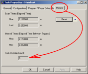
TIP: you might want to look into using the "Task Monitor Tool" to help answer these types of questions ... NOTE: that is NOT the same tool as shown in the figure below ... you can see a sample in the last figure of the post linked here:

http://forums.mrplc.com/index.php?showtopic=26162&p=125399

or – for a really quick (but non-conclusive) check – take a look at the figure below ... monitor WHATEVER task you have the "pulse counter" located in – and see what value is stored in the "Task Overlap Count" location ... if it's anything other than ZERO – then you need to find out why that task is being told to "start again" before it gets a chance to "finish what it already started" ... (that would fall into the "bad" column of things to worry about) ...

from realolman:

I have often wondered about the maximum frequency of many of these inputs and wondered how dependent they were upon things like the scan time of the logic

for most applications (starting pumps, motors, etc.) how fast you handle the field signals isn't all that important - (after all, what's a scan cycle here or there?) ... but ... when you work with faster operations (conveyors, speed controls, etc.) then moving the field signals in and out can become a critical issue ...

suggestion to the OP:

post your ENTIRE project file (.ACD) and we'll take a look at it ... (you'll have to zip it first – forum rule) ... if you're not allowed to post the file, we'll still try to help – but we need a lot more information to work with ...

good luck with your project ...

SIDE NOTE to other readers in the future ... this thread involves a CONTROL-Logix platform ... if this were a COMPACT-Logix platform then the discussion would be much more involved ... basic ideas: one size does NOT fit all – and the two platforms are NOT the same ...

.

task_overlap.PNG
 
Last edited:
Thank you Highland Controls,

Ron Beaufort, to answer some questions,

yes it is set to 0ms, and i had a look and yes i do have COS,
however both columns appear to be checked, is this normal?

The Ib-32 is local I/o,

i am using a 1769-L72 processor.

I have added the file for you to see also.( oh no wait, i cant seem to zip it small enough, i will post it as soon as i figure out how)
 
before you zip the file - use RSLogix to do a File Save As - and set the type for L5K (Library file) ... this is usually a LOT smaller format ...
 
ok here it is,
the encoder pulses are currently being fed to Local:5:I.Data.2, and the diameter calculation is being done on unwind block, sheet 27.

What this is used for is to measure the reel of material's diameter therefore speeding up or down the drive according to the size, and the program uses these pulses to work out the diameter
 
right now I'm burning midnight oil on another project - so I'm out of time right now ... but here's what I THINK about this problem so far ...

your original post mentioned a ballpark frequency of about 104 Hz for the signal ... according to my rough math – that works out to something like 0.0096 seconds per cycle ... let's call it 10 ms ... in order for a "counter" to count reliably it needs (rule of thumb) to be executed (by the processor) at least roughly twice as fast as its off-on cycle ...

based on that rule of thumb – you need to execute the counter at least every 5 ms ...

but ...

you have your Block task set for a period of 7 ms ... I'm willing to bet more than pocket change that setting is a big part of your "missing counts" problem ...

DISCLAIMER: I am TIRED right now – so my math may indeed be wrong ...

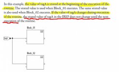
going further (and probably not as important) ... you're executing the counter in an FBD (Function Block Diagram) ... I suggest that you read up on how an FBD handles any input signals ... there's a quick excerpt shown below from page 12 – but you really need to read it all ... here's a link ...

http://literature.rockwellautomation.com/idc/groups/literature/documents/pm/1756-pm009_-en-p.pdf

so ...

based on all of that – it seems (at least from where I'm sitting) that any benefit that might have been derived from using COS (Change of State) on the input module is going to be rendered totally useless by programming the counting action inside an FBD ... I'm mentioning all of this because I've noticed that you're using that same input signal in at least two places in that same FBD - but I don't have time to track down any implications of that ... it might be OK - but it looks "fishy" on the face of it ...

all said and done – you might want to seriously consider using a High Speed Counter for this input signal ... AND ... seriously consider moving the logic out of the FBD and put it into a plain vanilla Ladder Logic routine instead ... AND ... worry about how often you need to execute whichever task you put the logic in ... AND ... worry about the priority of that task – and how that priority relates to the priorities of all of the other tasks in your project ...

I hope that this helps – I am out of time ... good luck with your project ...

.

FBD_inputs.jpg
 
Last edited:
It's late for me, and I'm tired also, but here's my take on it.

Enable COS for the pulse inputs ONLY for that input module, and you only need OFF to ON... Turn off the "Enable COS for diagnostic reporting" if it exists for your module.

Turn off the COS for all other I/O modules, default is ON, which means the RPI basically is a "worst case" update time. If the RPI is adequate, no point having COS enabled, it just hogs a network resource for no purpose.

Configure an EVENT task, triggered by the COS of that input module to do your counting.

That will get your pulse inputs "seen" by the logic effectively. How you use that count from there on is up to you, you could even trigger another EVENT task (Use the EVENT instruction) when the count exceeds a value, or whatever you need.

Slow the RPIs of other, less-critical I/O modules, most standard (digital) I/O modules default at 20mS RPI - if you don't need it, slow them down and relieve network resource.

I think you'll have greater issues trying to use the HSC modules for this application
 
OK, I am not a Rockwell expert, but I have used counter modules in other PLC's to read encoders without problems. The frequency limits are typically in the MHz range, so you won't be missing any counts. Trying to catch encoder pulses in ladder(or whatever logic) doesn't seem to make sense to me. Is the HSC in this PLC really that difficult to use?
 
On inspection today I have found that the second 1756-HSC module, apparently, has 2 unused inputs that are bridged out. I assume this is a standard requirement for unused inputs.(i didnt do the initial installation)
Anyway, it does now appear that I do have the option to connect the encoder to the HSC instead, then amend the PLC programme accordingly.

Can anyone suggest the correct procedure for this, is it simply take the cable of the encoder that currently goes to the IB32 and connect to the HSC and then change it in the PLC programme?
 
Is there a relatively simple estimate of the maximum number of pulses a 1756-IB32 can read ?

AB Technote: ID: QA53283

Answer
When change of state is configured Off to On, max frequency = 1 / 380 microseconds = 2.631 Hz.

Really is the maximum number of pulses 2 per second ?
 
Welcome to the PLCTalk forum community !

Ideally when you have a new question, even if it has been addressed in a past thread, use the "Start a New Thread" button and link to the older discussion with the hyperlink button, rather than posting directly to it.

That RA Knowledgebase document includes an obvious typographical error: the values are in kilohertz, not in hertz.

There are faster discrete I/O modules for ControlLogix and CompactLogix, as well as some with onboard "low speed counters" like the 1756-LSC8XIB8I.
 

Similar Topics

Hi... I'm working on a project where we are modifying an existing system. We are adding a 1756-ib32 input card to a spare slot on a existing rack...
Replies
4
Views
2,074
I am trying to wire a device which has 2 separate open collector outputs that need isolated channels to function properly to a 1756-ib32 discrete...
Replies
1
Views
1,550
Hi, I have AB DIGITAL INPUT type 1756-IB32/B. At the moment I want to test this module only ( separate / not connected from CPU ), is working...
Replies
1
Views
1,528
Hi, I have a ControlLogix system with 1756-IF16 analogue inputs. I can't scale the inputs at the card as there is a requirement to facilitate...
Replies
2
Views
77
Hi, I have two quick questions: 1- Could I use 1756-IA16/A with TTL inputs? Sourcing (PNP)? Sinking (NPN)? Either one? 2- What does /A in the part...
Replies
6
Views
147
Back
Top Bottom