how to connect analog senor 0-10V with delta plc

HamzaAhmed

Member
Join Date
Aug 2020
Location
Palestine
Posts
86
Hello guys,

I have a pressure sensor with 0-10 control and 0-600 bar range.
how can i read from it the signal and transfer it to bar and stored it in a register?

i think it is easy but i didn't do it before.

i am using delta plc.

Thanks,
 
Scale with parameters is what I would use with Allen Bradley. Zero would be 0 (0V) and 600 (10v) would be about 32700. Just a rough guess.
 
Scale with parameters is what I would use with Allen Bradley. Zero would be 0 (0V) and 600 (10v) would be about 32700. Just a rough guess.

Thanks for replaying, but how can i read from it by WPLSOFT and tell the software that the 0 equal 0 and the 10v equal 32700?
 
Choose a register for your raw value. That will be 0-32700ish. Then scale it to 0-600 and move it to another register. Use that register in your HMI. I don't know if your software has a SCP (scale with parameters) function. If not there are quite a few threads here with the proper way/math to scale without the PLC doing the work.
 
If the input is 0 at 0V and your scaled output minimum is 0 then you can do a simple divide:

DIV Input 54.612 Output

If the max input is 32767 that divisor would give you 600.

Now, Automation Direct max values are a lot lower, and some AB readings can be 16382, so give your input a 10V signal and see what the raw value is. Then divide the raw value by the new max of 600 and use that in the above calculation. Plus if your analog input is reading a little off it is better to find the actual readings, then scale.

If either of the minimum values is NOT 0 then you would have to do the scaling calculations that are in quite a few threads here as 77nomad suggests.
 
Choose a register for your raw value. That will be 0-32700ish. Then scale it to 0-600 and move it to another register. Use that register in your HMI. I don't know if your software has a SCP (scale with parameters) function. If not there are quite a few threads here with the proper way/math to scale without the PLC doing the work.

I know how to save the value from the sensor in a register, but the value is not the pressure value it is something else. i can calculate the value and turned it to a pressure by my hands.
but how can i do that in PLC? how could the PLC understand that the x value means 400 bar for example.
 
If the input is 0 at 0V and your scaled output minimum is 0 then you can do a simple divide:

DIV Input 54.612 Output

If the max input is 32767 that divisor would give you 600.

Now, Automation Direct max values are a lot lower, and some AB readings can be 16382, so give your input a 10V signal and see what the raw value is. Then divide the raw value by the new max of 600 and use that in the above calculation. Plus if your analog input is reading a little off it is better to find the actual readings, then scale.

If either of the minimum values is NOT 0 then you would have to do the scaling calculations that are in quite a few threads here as 77nomad suggests.

Pretty good, could you give me these steps by mathematical way?
 
Pretty good, could you give me these steps by mathematical way?


wow, twice in one day.


https://www.plctalk.net/qanda/showpost.php?p=841644&postcount=10


Many PLCs will have a built-in scaling instruction, where you put in the four values (Y1, Y0, X1, X0) as (constant) configuration parameters, and then use the "sensor register*" as the dynamically changing input, and the scaling instruction calculates the output on each scan.


* often referred to as "raw counts," "Data Number" or "DN," etc.
 
Last edited:
wow, twice in one day.


https://www.plctalk.net/qanda/showpost.php?p=841644&postcount=10


Many PLCs will have a built-in scaling instruction, where you put in the four values (Y1, Y0, X1, X0) as (constant) configuration parameters, and then use the "sensor register*" as the dynamically changing input, and the scaling instruction calculates the output on each scan.


* often referred to as "raw counts," "Data Number" or "DN," etc.

Thank you, but i didn't understand this part
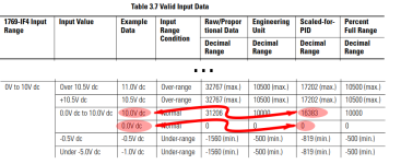
Furthermore, the 0-10V signal into the analog input of the PLC is converted to a numeric value, which I will call a Data Number, or DN. For this example: at 0V, the DN is 0; at 10V the DN is 16383; so 16383DN is the same as 10V

what is this number?!
 
Hamza, I suggest you find the manual for the analogue card you are using.
This will give you the wiring, configuration information and the values for the range selected, It depends on the card & PLC platform and there will be documentation on the values for 0-10V an example could be 0-16384 again it will depend on the resolution the card i.e. it could be 12 bit or 16 bit, 16 bit in theory could give -32767 to + 32767, some cards are configurable to the resolution.
Here is some information
https://instrumentationtools.com/how-a-plc-do-the-scaling-for-a-sensor/
As already stated, most modern PLC's will have a function to scale the raw data value to the required value. there are a number of ways to do it You will probably find that linear scaling is the one you need for the formula, you only need more complex ones for sensors that are not linear or for example a level control on a round tank that is horizontal or a cone shape.
You really need to tell us what model PLC as there are a number of types some have built in analogues others require additional cards. so what PLC, If an add on analogue card what part number.
There seems to be little information on the Delta website, little or no accessible information however, I did find this.
http://profsite.um.ac.ir/~shoraka/Delta PLC Applications Programmig.pdf
I now remember that the Delta is almost identical to the Mitsubishi PLC range in fact when you look at the memory maps, instructions etc. there appears to be little difference.

Thank you very much, i understood most of things.
 
Thank you, but i didn't understand this part


> Furthermore, the 0-10V signal into the analog input of the PLC is converted to a numeric value, which I will call a Data Number, or DN. For this example: at 0V, the DN is 0; at 10V the DN is 16383; so 16383DN is the same as 10V


what is this number?!


What I called Data Number or DN there, is often referred to as the "raw counts," or just "counts," value that an analog input module passes to the PLC.


An analog input module has channels, and each channel performs an "Analog to Digital Conversion;" such devices are often called A/D or ADC. The analog part is an incoming external signal that is usually electrical in nature, such as a a voltage or a current; the digital part is "raw counts" an integer that is passed to the PLC program input memory location, and binary value of some number of bits, which value is linear with the analog signal. In the example above, if the incoming analog electrical signal is 10V, then the digital counts value is 16383.


For a 16-bit module, the counts value is usually* in the range -32,768 to +32,767; for a 14-bit module, it might be in the range 0 to 16,383. For the exact meaning of the value you need to refer to how the module itself and its configuration; in the example above I assumed it was similar to an Allen-Bradley 1769-IF4 or 1769-IF8 configured for 0-10VDC with [Scaled-for-PID] as the [Input Data Selection Format] cf. here and below.

* also sometimes 0-65,535


xxx.png
 
What I called Data Number or DN there, is often referred to as the "raw counts," or just "counts," value that an analog input module passes to the PLC.


An analog input module has channels, and each channel performs an "Analog to Digital Conversion;" such devices are often called A/D or ADC. The analog part is an incoming external signal that is usually electrical in nature, such as a a voltage or a current; the digital part is "raw counts" an integer that is passed to the PLC program input memory location, and binary value of some number of bits, which value is linear with the analog signal. In the example above, if the incoming analog electrical signal is 10V, then the digital counts value is 16383.


For a 16-bit module, the counts value is usually* in the range -32,768 to +32,767; for a 14-bit module, it might be in the range 0 to 16,383. For the exact meaning of the value you need to refer to how the module itself and its configuration; in the example above I assumed it was similar to an Allen-Bradley 1769-IF4 or 1769-IF8 configured for 0-10VDC with [Scaled-for-PID] as the [Input Data Selection Format] cf. here and below.

* also sometimes 0-65,535


View attachment 55320

Thank you so much, i understand it easely.
 
The Delta PLC is not like AB, It depends on what PLC type I believe the smaller brick ones have built in analogues, if you read the manual the values (assuming 2 or 4 channels) are automatically assigned to D Words I believe in the 7000 range, The modular PLC's that use Adapter cards (originally) you have to use A TO instruction to write to the card (Configuration) and From instructions to read from the cards. The cards use what they call buffer memory, these In Mitsubishi are BFM numbers (I think on Delta they may be called something different) for example a To instruction something like [TO K0 H3333 K1] will Write to card 0 Hex Value (Setting for 4-20ma) to Buffer Memory 1 the From instruction will fetch data from the buffer memory for example to get the 4 channels of data
FROM [ K0 K9 K4 D100] Will fetch the 4 channels of the analogue value from card 0 BFM 9 (Analogue data) and store them in D100-D103. The buffer locations in Delta may be different and this was off the top of my head but again the manual will show it. There are many buffer locations probably 200+ or so for settings, values etc.
There is also a hardware config software so you do not have to use plc instructions to configure or fetch data from the card. I have just remembered, the Delta buffers are called control registers (CR).
Again without knowing the model number of the PLC it is impossible to say what the analogue values are

Thanks for your replying,
i can read and write from the analog input card but the question was how can i know what this value means?
if i read value 500 for example from the card what this value means. if i know it i can deal with it and convert if as i wish.

this is the question how to know what the value mean.
 

Similar Topics

Hi, I am working on a project with Delta PLC for the first time. I want to connect a Sinking analog sensor (4-20 mA) to a Delta analog module...
Replies
0
Views
1,661
Hi, Calculation of voltage drop of a 2 wire transmitter connected to plc AI is pretty simple and straight forward. My Question is could you...
Replies
4
Views
2,129
I have a very simple program which is run by a 2080-LC10-12QWB Micro810 PLC connected to a single sensor. The sensor has two outputs, one which...
Replies
3
Views
4,843
Hey, We have a 3-wire 4-20mA sensor that is connected to a display like this Now i need to connect this to a siemens ET200S analog input...
Replies
4
Views
2,926
I need some help with wiring a DCT200-42-24-F DC Transducer to a AB 1769-IF8 Analog Module in a CompactLogix PLC. I thought it would be pretty...
Replies
3
Views
4,733
Back
Top Bottom