Sensor Value Conversion

johnsmith

Member
Join Date
Sep 2022
Location
Kl
Posts
9
Hi Everyone,

I have bought a Temperature and Humidity Sensor combo and I'm not sure how to covert them to actual (C*) and (RH) unit.

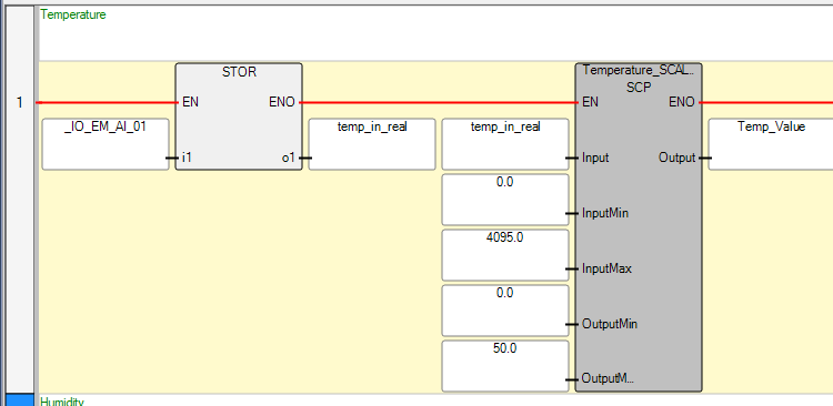
I have connected it to my Micro820 and I get some readings from them using connected component software. But I'm not sure what these values mean. Like is it voltage difference or what??

I have attached the translated manual for the sensor

Image of Connected Component software showing each of the sensor's output values:
https://freeimage.host/i/HKvA929

Link to the sensor:
https://www.aliexpress.com/item/4001310289075.html?spm=a2g0o.productlist.main.39.2cb7604dzrx0iL&algo_pvid=e66a2da9-9204-42cf-a97c-eb7bd61c1e3a&algo_exp_id=e66a2da9-9204-42cf-a97c-eb7bd61c1e3a-19&pdp_ext_f=%7B%22sku_id%22%3A%2212000015584580815%22%7D&pdp_npi=2%40dis%21USD%2129.0%2125.23%21%21%21%21%21%4021227a0f16671968348543938d078c%2112000015584580815%21sea&curPageLogUid=Ef0Xf5smV6b3

Capture.PNG
 

Attachments

  • translated manual (1)_compressed.pdf
    69.9 KB · Views: 16
So, page 2 of your linked manual has the formula you need. you'd then use a similar formula to convert the values you see into Voltage and apply it there.

However, you can use the NORM_X and SCALE_X instructions in the Siemens PLC.
 
So, page 2 of your linked manual has the formula you need. you'd then use a similar formula to convert the values you see into Voltage and apply it there.

However, you can use the NORM_X and SCALE_X instructions in the Siemens PLC.

Yeah I'm aware of the formula in the manual. But my original question is that the value from sensor is what exactly. Is it a voltage or some other representation.

The value that I got is shown in the screenshot provided, for both temperature (T) and Humidity (H)
 
Assuming your sensor is 0-10v & you are using an analogue input of 0-10v & the tepmerature range is say 0-50 Deg C & your analogue range is 0-10v = 0-4095 then the maths is simple.
Temperature (℃) =
4095/50 = 81.9 per deg c.
so asuming your lower limit is 0 Deg C then there is no need to worry about lower limit.
So if your sensor is reading 25 deg C then you should have a count of 2047.5
2047.5/81.9 = 25 Deg C
i.e.
(((Scaled Max-Scaled Min)/(Max Raw Input-Min Raw Input))*(Raw Input-Min Raw Input))+Scaled Min = Scaled Value
 
Re-stating what others have said in another form ...

In that formula:

- Replace the [Actual Voltage(V)] with the Measured Physical Value (e.g. 2502 for _IO_EM_AI_00).

- Replace the [10] with [4095.0]


In other words,
- when the electrical analog input is 0V, the Measured Physical Value will be 0.
- when the electrical analog input is 10V, the Measured Physical Value will be 4095.
- when the electrical analog input is between 0V and 10V, the Measured Physical Value will be between 0 and 4095, and will behave linearly with respect to the analog input voltage.

You need to have a sense of proportion.
 
Here is a simple conversion, note: there will be a minor error (to do with floating point errors in the PLC & 4095, to reduce the error could use 4096 but it is so small it will not matter, it takes 3 rungs first converts the raw analogue value into a float (Real), the second finds the raw counts per degrees C (could be any type of measurement i.e. PH, Flow etc.) the third divides the raw analogue value by the value per deg. C to give the scaled value.
Note: to make it simple and if you have no negative value i.e. -25 Deg C then there is no need to include the subtraction of the min value as it would be 0, also note the last rung, this replaces the second & third rung by the number of counts per deg. C (simply use a calculator to find it & make it fixed), however, sometimes it makes sense if you have an HMI with an engineering screen to make the min & max of the RAW & Scaled values so these cam be altered to perhaps a different sensor or raw count. Many PLC's have a scaling block (Function) built in or do it by setting parameters in the anlogue card setup.

Simple Scaling.png
 
Thank you everyone for your help, really appreciate each one of you. So little update I managed to use SCALER block in connected component to help me convert the analog input to EU as shown in the picture.

The NORM_X and SCALE_X concept from @cardosocea helped alot.

HKbDc5F.png
 

Similar Topics

Hi all, I am working with an IO link sensor (measuring current across motor)and need to read in and store the sensor values for 5 seconds, then...
Replies
13
Views
1,200
I'm new to S7/TIA. There's no devices connected to the PLC yet. I've got a laser measurement sensor (Micro-Epsilon optoNCDT 1220). From the...
Replies
18
Views
2,937
Hi. I'm new to allen bradley PLC's and PLC's in general. I've been asked to make a program that can determine the water flow of a machine. I...
Replies
7
Views
1,684
Im installing a sensor setup that has only NPN sensors. The sensors count jars that pass by them. The sensors do not control any equipment. The...
Replies
10
Views
8,195
im using DVP-04pts and here is the download link to see its output...
Replies
5
Views
1,852
Back
Top Bottom