Allen Bradley Flex I/O erreur programme

dawars

Member
Join Date
Nov 2022
Location
Angoulême
Posts
32
Hello friends,

I preferred to make a new post because the subject is not the same and I will see in time if my situation is good to put the old post as solved.

So I wanted to put the gml program in my imc-s provided by the manufacturer.

But I have a small error message talking about flex I/O. I don't really know what these modules are but I think I have found the hardware in question. I share a screenshot and a photo of the mobules.

I think the second module seems to be without power (no led on) I checked the plugs and I have voltage, I believe 25V dc.

Again I don't understand, the 25v gives the power supply to the module or does it have another power supply? Because the other mmodules seem to be good anyway.

I also may have done something wrong before in handling before uploading the program.


Currently it is on the right and I have already tried unplugging and reconnecting. I'll have to test it with a multimeter I think.
 
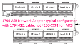
The most common arrangement of FLEX I/O was with a network adapter on the left, and the modules numbered from left-to-right.

But when a "backplane extension" cable was used, the number order was reversed for the modules connected to it, as shown in the attached snip from the FLEX network adapter user manual.

By contrast, the IMCS user manuals suggest that the special cable made to connect FLEX to the IMCS should be plugged in on the *left* side of the FLEX I/O adapter, which would be consistent with your left-to-right numbering.

If your system is not physically connected as indicated by the user manuals, try reversing the module order in your GML program or moving the cable to the left side of the assembly.

FLEX extension cable.PNG
 
With regard to the 2nd module (the green-labeled 1794-OB16): it appears normal for a program that is not commanding any outputs to be turned on.

That is a 24V discrete output module with 16 outputs.

The module electronics get their power and communications across the FLEX bus.

But the outputs themselves get their power from an external supply connected to the middle row (V Common) and the bottom row (+24V). You can see the wiring diagrams in the Installation Instructions, publication 1794-IN094.

There are no "control power present" or "module active" LED indicators on that module, only the 16 individual output channel status LEDs.
 
I tried to understand and but not easy for me haha. I checked the flex i/o cable, it looks ok, this cable connects to the left of imc-s at the top with a very special plug. the cable will then plug into the last module to the right of the photo I posted just before.

If I understand correctly for the history of the leds which do not light up is therefore normal if the imc-s does not say anything.

Okay this is going to be complicated now. If the Imc-s does not say anything then there is another problem on the imc-s or the program is not the right one, I would have to manage to put a gml file in the imc-s. But at the moment I have this error..

The modules if it breaks down let's say this example, I risk having a communication problem? I'm trying to pinpoint where the problem is coming from. I will try to have a plan of the socket to know which plug uses for the signal and go back to the electronic card to find out if there is a component problem.

Sorry again if I can't be clear on my sentences in English
 
I forgot to say too. How can I check the gml file for the module? I do not know how to navigate in this software with the manufacturer's program
 
Hello, I am still continuing my research on the flex problem.

The connection of the flex is done with all the modules or precisely with only one in particular?

Is there someone who knows the electronics of the chip that manages this connection?

I checked the flex cable and the imc-s plug, everything is good.
 
I searched a bit in the flex configuration. And I came across the connection parameters.

I imagine that the names of each module are displayed here.

AND I can understand the input and output here if I'm not mistaken.

And if I understand everything then I think there is no problem here?

If I uncheck the modules, the program will work without the modules selected to send the program to the imc-s?

https://scontent-cdg2-1.xx.fbcdn.net/v/t1.15752-9/319983731_487418459945192_5227101037074721779_n.png?_nc_cat=107&ccb=1-7&_nc_sid=ae9488&_nc_ohc=4jI45c6N2xgAX-ZV0dD&_nc_ht=scontent-cdg2-1.xx&oh=03_AdR0i3R347-69z0mXZXCY8tkGtr8Bbqppb6qPxxcVMwOVg&oe=63C53039


Ok, I think I understand. After finding the module names, I would have to compare the selected models to see if it matches.


https://scontent-cdt1-1.xx.fbcdn.net/v/t1.15752-9/318780811_1385400162005136_2856195244971392901_n.png?_nc_cat=110&ccb=1-7&_nc_sid=ae9488&_nc_ohc=qalTZqkoAlAAX-Q81at&_nc_ht=scontent-cdt1-1.xx&oh=03_AdQhoS2-ET7uw1HB5jv3KE9fGs0xiaN7RL99lphht7p_8Q&oe=63C51E7F
 
Last edited:
I searched a bit in the flex configuration. And I came across the connection parameters.

I imagine that the names of each module are displayed here.

AND I can understand the input and output here if I'm not mistaken.

And if I understand everything then I think there is no problem here?

If I uncheck the modules, the program will work without the modules selected to send the program to the imc-s?

https://scontent-cdg2-1.xx.fbcdn.net/v/t1.15752-9/319983731_487418459945192_5227101037074721779_n.png?_nc_cat=107&ccb=1-7&_nc_sid=ae9488&_nc_ohc=4jI45c6N2xgAX-ZV0dD&_nc_ht=scontent-cdg2-1.xx&oh=03_AdR0i3R347-69z0mXZXCY8tkGtr8Bbqppb6qPxxcVMwOVg&oe=63C53039


Ok, I think I understand. After finding the module names, I would have to compare the selected models to see if it matches.


https://scontent-cdt1-1.xx.fbcdn.net/v/t1.15752-9/318780811_1385400162005136_2856195244971392901_n.png?_nc_cat=110&ccb=1-7&_nc_sid=ae9488&_nc_ohc=qalTZqkoAlAAX-Q81at&_nc_ht=scontent-cdt1-1.xx&oh=03_AdQhoS2-ET7uw1HB5jv3KE9fGs0xiaN7RL99lphht7p_8Q&oe=63C51E7F

After verification everything is good, from left to right the reading of the modules with the correct model.

I continue to search and then check the imc-s card. I will maybe try to write to the manufacturer allend bradley if he can provide me with the electrical diagram of this card in passing.
 

Similar Topics

Got this new to me powered on today and have no main air and the only problem I have found is the f059 on the vfd. S1 has 24v, none on S2, and 48v...
Replies
10
Views
473
Greetings everyone, I know there is a way to programmatically set the date/time on a 750 series VFD (look up Rockwell automation sample code)...
Replies
1
Views
1,042
Can someone do me a huge favor and print these 2 Allen Bradley DNO files and email them to me? [email protected]...
Replies
1
Views
1,754
Hi all, Client with a pretty much brand new AB Powerflex VFD starting throwing Fault 17: Input Phase Loss this afternoon. Started doing some...
Replies
6
Views
9,479
We have a Powerflex 753 drive on a 192.168.1.X network that I can communicate with a Controllogix L71 with no issues on same network...
Replies
0
Views
1,434
Back
Top Bottom