SLC 150 RST Instruction

BradSensenig

Member
Join Date
Apr 2012
Location
PA
Posts
18
I am currently converting a SLC 150 program to a RSLogix 500 program (MicroLogix 1400). In the SLC 150 program there is a timer (901) that has 16 RST instructions tied to the same timer. Under each RST instruction there is RE and then a value. The RE valve is different for each RST instruction. I am not sure what the RE means and how it effects the timer.

I have attached a copy of the program. I am specifically looking at Rung 017 (where the timer instruction is located), and Rungs 019 - 033 (where the RST instructions are located).

I understand that an RTO instruction needs the RST instruction to reset the RTO. I'm wondering why there is 16 RST instructions for the same timer and what the RE is so I can convert accordingly.

Thanks in Advance.
 
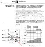
Is this RST for a normal RTO timer, or maybe for a High Speed Timer or an SQO sequencer? The 150 had both and these also used RST to reset the counter functions.

For the normal RTO, the RST had a parameter RAC "Reset Accumulator value" which controlled WHAT VALUE the timer was reset to. Normally it is RAC 0000, but RAC could also be any value from 0 to the timer PReset value.

SLC150  RTO Timer.JPG
 
Last edited:
Brad,

Apparently your program was using the RST function to reset the same timer to different time Preset values (therefore effectively creating a new timer with a time setting of PReset minus the RAC value, to get around the limited number of timers available in the SLC150). An equivalent instruction in a modern ML1400 would be to use the same rung triggers to MOV the time value RAC to the timer T4:X.ACC accumulator where X is the timer number. A less-confusing alternative may be to MOV the (PR-RAC) of the old program to the new timer T4:X.PRE value.

An even better solution for your converted program might be simply to create a new timer for each different RAC setting.
 
Last edited:
thank you for your response. I just want to clarify to be 100%. I saw the manual and under the example RST instruction I see the RAC is to set the accumulator back to 0 or another valve. The RST instruction in the program I'm trying to convert, that I posted, has an RE under the RST instructions not RAC. Is it same ti assume that they do the same thing-resetting the accumulator to certain valve?
 
I have not been able to find the "RE". That must be a later version of the SLC150. It almost had to be doing the same thing (resetting the timer accumulator value), maybe using a stored value from some memory location "RExxxx". I do remember that RE was a command on the old SLC100 hand-held programmer to REmove a line or instruction from the program
 
Last edited:
ok,thank you. That makes sense- unfortunately I don't have the SLC 150 where this program came from to verify. I can tell you I am using PCIS Ver. 2.0 to view the SLC 150 program.
 

Similar Topics

How can I get a schematic for it? I am unable to communicate to it using PCIS with a 486 PC and suspect the SLC150 to be faulty (found in a junk...
Replies
11
Views
3,082
HELP! I've been searching & searching for the software to run my SLC150 PLC for DOS 6.22 and for some reason, every link I have found for it -...
Replies
4
Views
1,148
Hi, I have an old SLC 150 processor that is throwing up a CPU Fault light. I have an EEprom program chip for it, but I can't get it to load up...
Replies
4
Views
2,312
We have 3 SLC-150s that we are using, we would like to create a print for them and diagram the program so when we get approval we can replace them...
Replies
4
Views
2,640
Hello, I am completely new to PLC's (and forums) and have been tasked to repair/upgrade a conveyor system at my college. It currently has an Allen...
Replies
9
Views
2,682
Back
Top Bottom