Ryan_Flowers
Lifetime Supporting Member
Hello all!
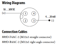
I need to install an 837T Temperature Transmitter (837T-N1N14B25A-D4 to be specific). it is a 4 pin connection. This is reading temperatures and sounding an alarm if out of tolerance. My problem is that I get no 4-20mA signal in from the transmitter in my logic at the input table for channel 0 or any other channel I connect it to. The card is configured for channel 0 to be 4-20mA and be raw/proportional data format. The temp transmitter is connected with a quick disconnect 889d-r4ac-10 four wire cable as follows from my main enclosure:
Black = - DC
White = + DC
Brown = + 4-20mA Signal
Blue = - 4-20mA Signal
My PLC is an AB 1766 Micrologix 1400 with an AB 1762-IF4 analog input module. I tested the other channels with a current loop simulator and got the necessary data at the input table for 4-20mA.
I may just be confused on the wiring, but I would appreciate the help.
Thanks


