BSL Example

TheWaterboy

Lifetime Supporting Member + Moderator
Join Date
May 2006
Location
-27.9679796,153.419016
Posts
1,924
Can anyone provide a simple example of a BSL with a single bit walking down a 2 DINT array, stopping somewhere in the second dint and starting over. I keep getting an incrementing value as all the bits remain high.
I have a lot going on this week and this one thing is making me question my sanity.
 
to do what I understand from your description, the bits loaded into the array have to be a single 1 bit and the rest must be 0s.


Control/CompactLogix? MicroLogix? Micro800? Summat else?
 
[Update: better image]


What does yours look like?


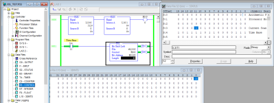
Here's my example (MicroLogix 1100):


  • Bit S:4/11 has a rising edge every ~410ms
    • S:4 is 16-bit 10kHz free-running clock
  • That rising edge triggers Control R6:0 to BSL (push) a bit onto the L10 file at L10:0/0
  • Rung 0000 ensures only one bit is 1 in the first two DINTs of L10.
  • R6:0.LEN should be 0, but I put 65 in the out of curiosity
    • The overflow bit keeps moving through L10:2 and disappears after L10:2/15, which makes sense
Adding a [XIO L10:1/15] (e.g.) to Rung 0001 would disable the BSLs after the 1 bit shifts from L10:1/14 to L10:1/15.

yyy.png
 
Last edited:
I will try and help you understand
While its been a long time since I did a Bit Shift they haven’t changed
You refer to the value of the DINT incrementing with each step, well just forget the word values altogether the word values will be what the bits in the word are. You will confuse yourself trying to work with the words.
All words in a PLC or computer are all made up of an array of bits
A bit an only have one of 2 values 1 or 0, True or False those are the only values you need to deal with
Understand that bit shift’s are edge triggered functions when the rung goes from false to true the function executes. And shift’s all the bits to the left I place or right depending on the function BSL or BSR On shift Left on 2 DINT words, the value of bit 63 is lost (Falls off the end) the value of bi t 63 in replace with bit 62 and then the value of bit 62 is replaced with the value of bit 61 this repeats to bit 0 there the value of bit 1 is replace with the value of it 0 and finely the value of bit 0 is replaced with the value of the input bit.
This process repeats every time the rung goes from false to true if the input bit remains 1 then each tie the rung goes true the a 1 will be mover to the bit to the left so it is important to be sure the input bit is either set or cleared between the rung executions. And the rung must return back to false to start the next shift.
While with most Bit Shifts input is at bit 0 it is possible to set or clear the bits with ing the shift array word. If you clear a bit in the word on the next execution of the bit shift function the value of 0 will moved to the next bit to the left (higher) and the same would be true if you set a bit in the word then the next bight (higher) would be set to 1
Whatever the bit value at the time of the shift that is the value that is set in the next bit
Typically this would be on an inspection line a bit is set to 1 when a part is placed on the line and at each inspection point if it fails the bit is cleared at the end of the line if the part is good (1) it is passed to the nest station if it is no good (0) then it is dropped off the end in the trash

From your description it sounds like you input bit is not changing state so it is always passing the value of 1 on each shift

I hope this helps
 
...This process repeats every time the rung goes from false to true ... And the rung must return back to false to start the next shift. ...


Just to muddy the waters (so don't read this until you complete GaryS's post fully):


A more specific way to state this is that the process repeats when

  • The BSL input rung is true
  • AND
  • The CONTROL.EN bit is 0
Also, whenever the BSL input rung is true or false, the CONTROL.EN bit will be assigned 1 or 0, respectively, each time the BSL instruction rung executes.

That is, the [BSL input rung + the CONTROL.EN bit] compose a one-shot, where the CONTROL.EN bit is equivalent to the storage bit of a one-shot instruction (e.g. ONS or OSR).

So strictly speaking, to have the BSL do the next shift, either

  • In the normal case the input rung has to return back to false and then true again i.e. rising edge, as noted by GaryS
  • OR
  • In a special case the CONTROL.EN bit has to be assigned 0, so on the next scan the input rung still-true state will appear to be a rising edge.
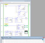
See below; when L10:0/7 (L10:0=128) is 1 and that 1 is shifted to L10:0/8 (L10:0=256), the next 7 BSL shifts will occur on the next 7 scans because Rung 0003 will clear CONTROL.EN after the BSL, so the BSL will detect a rising edge condition, on those next 7 scans, until the 1 bit gets to L10:/15 (L10:0=65536).
yyy.png
 
Drbitboy
the unlatch of R6:0.EN dose absently unnecessary
In all functions when the proceeding rung evaluates to true the function .EN is set to true
and the function executes the bits are shifted.
and if the rung evacuates to false the function .EN bit is set to false and the function will not execute and the bits will NOT be shifted
The function can only execute if it’s .EN bit is true.

In your example the Time Base S:4.13 will only be true for 1 scan of the ladder program then it will be false until the nest time base rolls over. So in this case the time base will be True – False – True - False stepping the BSL through the bit array.

You could make it work differently
I would not recommend this but it will work
Place the BSL in an unconditional rung ( it would always be set to true when the ladder executes that rung) and the BSL would shift the bits 1 position .
Then someplace else in the ladder program unlatch the R6:4.EN bit
The next time the BSL evaluates the .EN bit would be set and the BSL would shift the bits
 
I have not absorbed this all thoroughly yet (will later today after a stream of web meetings) but my BSL does not yet proceed into the second DINT. (Wish I could use a 64 bit LINT)
 
Last edited:

@TheWaterboy: ignore this for now, but my motivation is similar to this sentiment.


@GaryS:

Oh dear, like I said, I muddied the waters; perhaps that was unwise. Well, one or both of us is going to learn something ...

Except for the first sentence and maybe one or two others, I don't disagree with anything in @GaryS's last post post.


  • Regarding the first sentence I think there is a misunderstanding of the point of my post and/or of the program.
    • Specifically, the intent is to typically shift the bits every ~1638ms, i.e. when S:4/13 has a rising edge, but to also shift the bits every scan when the 1 bit is within a certain range of bit positions.
  • "the Time Base S:4.13 will only be true for 1 scan of the ladder program then it will be false until the nest time base rolls over"
    • I disagree here: S:4/13 is 1 for ~819ms, then 0 for ~819ms, as long as the PLC is in RUN mode.
    • Maybe what was meant was that "[the BSL-detected rising edge] of its input rung will only be true for one scan ..."
      • and with that I agree, although it is only true in typical operation i.e. if nothing fiddles with CONTROL.EN/.DN
  • The purpose of the program was to typically shift the bits every ~1.683ms, but to shift the bits every scan when the 1 bit was between L10:0/8 and L10:0/15.
    • The purpose in turn for doing that was to demonstrate that the [BSL-detected "rising edge"] that triggers each bit-shift is not strictly based only on an [actual 0-to-1 transition of the rung] during one scan, rather it is based on
      • the stored value of that rung from the previous scan, as measured by the state of CONTROL.EN/.DN, being 0
      • AND
      • the state of the BSL-input rung being true

  • Regarding the last paragraph, with the unconditional rung feeding the BSL, I agree it would work as described, but the movement of the 1 bit would not be visible in RSLogix Online mode, which is why I limited the one-shift-per-scan behavior to only a few of the bit positions.
P.S. I hope I got the timing of S4:4/13 right; my logic is that

  • the high bit (S:4/15) should complete a 1,0 cycle every 6553.6ms (2**16 steps of a 10kHz clock).
  • S:4/13 is a factor of four faster, so ta complete 1,0 cycle should take 1638.4ms.
If I got it wrong, then whoops, but that does not change anything else I wrote.
 
I have not absorbed this all thoroughly yet (will later today after a stream of web meetings) but my BSL does not yet proceed into the second DINT. (Wish I could use a 64 bit LINT)


Can you upload at least an image or PDF of your code? Specifically

  • Is the array at least two DINTs long?
  • Is the length parameter at least 33? CONTROL.LENGTH is the number of bits, not the number of DINTs.
I.e. one reason that the bits don't make it into the second DINT could be if the CONTROL.LENGTH parameter is 2 (the length of the array in DINTs, rather than in bits): in that case the second bit, dint_array[0].1, would be placed in CONTROL.UL after each shift, but the 1 bit would continue shifting to the next 16- or 32-bit boundary.


In my MicroLogix example, I used CONTROL.LENGTH=65, so the bits were shifted into the third DINT (LONG), i.e. to bit L10:2/0, and I also observed that, on each shift, the 1 bit at that last bit continued to shift through L10:2, until it reached the next 16-bit (word) boundary at L10:2/15.


"Take care of the bits, and the nibbles, bytes, INTs, DINTs, and LINTs will take care of themselves."
 
Last edited:
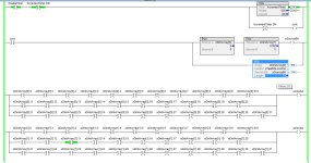
32 in the length and the bit stops at DINT[0].
33 in the length and the bit goes all the way through DINT[1]
You can see that bit 13 of the second DINT is true even though the length is 33

BSL.jpg
 
32 in the length and the bit stops at DINT[0].
33 in the length and the bit goes all the way through DINT[1]
You can see that bit 13 of the second DINT is true even though the length is 33

Interesting. At what point does .UL go high? When the bit reaches the 34th position? Or when it shifts out the end of the second DINT?

EDIT: Based on instruction reference manual, .UL is set by the bit unloading from the point specified by your length, and remaining bits in the array are 'invalid'.
 
Last edited:
Good, so you got the bits to shift into the second DINT.


Was it the xTestBSLControl.LENGTH that was the problem before?
 

Similar Topics

Would anybody have an example of a BSR or BSL. I would like to set up a shift register to check product on a turning device, so I can activate...
Replies
2
Views
3,114
B
Help Please, I need to track bad parts during assembly form one station to the next, I have to track through 16 stations and then eject either...
Replies
4
Views
5,062
Hi all, I am trying to convert RSLogix 5000 program to Step7. I need to bit shift left my array of double integers for tracking the product on...
Replies
2
Views
519
I’m working on a conveyor project for work. We’re trying to install a few diverts to carry product directly to one of two trailer doors. I have...
Replies
5
Views
1,049
Hello friends, When I trigger once for an application, I want to shift the 15th bit in the word address by 10 bit , so; 1000 0000 0000 0000 ->...
Replies
3
Views
1,666
Back
Top Bottom