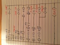
Ya but it’s not counting anything if there’s nothing after 5 objects pass. Right or no? Hmmm so the proximity sensor might scan a passing object or something while the conveyer is paused? Or is it just good practice? Then if there’s an extra count before reset won’t it be reset anyway? Sorry can you explain. I have conveyer run above counter rung. The more I go over it the less I understand it. So you think on my 3rd rung X3(NO) then I should insert |Y0| before [C1 K5] ? This helps troubleshooting?
You are using an out of date browser. It may not display this or other websites correctly.
You should upgrade or use an alternative browser.
You should upgrade or use an alternative browser.
New student
- Thread starter AC/DC/PLC
- Start date
Steve Bailey
Lifetime Supporting Member + Moderator
That suggestion was meant to prevent spurious counts when the conveyor isn't running. The sensor that detects objects on the conveyor probably can't tell the difference between actual objects and other things that might pass in front of it.So you think on my 3rd rung X3(NO) then I should insert |Y0| before [C1 K5] ?
My comment about troubleshooting was in regard to my suggestion to put the counter reset rung immediately following the counter. Someone trying to troubleshoot issues with the object count will probably want to know the conditions under which the counter is reset. Having the logic controlling the reset right after the counter rung instead of having to look for it several rungs later makes his job easier.This helps troubleshooting?
Both of those comments are more about matters of style. Your program may work fine without them when everything on the machine behaves as expected. The real challenge is to be able to gracefully handle things when they don't behave as expected.
And once again I have to ask if you understand the way the PLC works. Some of your comments have made me suspect you don't have a firm grasp of that.
Step 1: The PLC reads the data from the hard wired inputs.
Step 2: Armed with the latest input data it evaluates each rung of the program in sequence.
Step 3: It updates all of the hard wired outputs.
Step 4: It does some housekeeping.
Step 5: It goes back to Step 1 and repeats the sequence.
It continues like that until something or somebody tells it to stop. Each loop through the sequence takes somewhere between a few hundred microseconds to a few dozen milliseconds.
There are exceptions to that sequence but at this stage of your learning curve you should not be worrying about them.
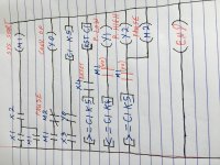
Thanks Steve, your correct I don’t fully understand how a PLC works but I know a small bit. Like exercise 1 and 2 that day I was able to answer. My lecturer practically did question 3 for me because I wasn’t grasping it and I brought question 4 home. He told me that the original line that I crossed out (the one ye guys were happy with) was the wrong way of doing it, so I brought in the M3 to add to the reset as I figured he wanted Y2 to be true as a condition of the reset. I don’t have that in my most recent attachment. Then he told me to finish it in class next fortnight and I suppose I went off on a tangent trying to figure out how to enter more rungs so I could get this exercise finished so that I could learn it. Which is probably why I came across even more confused then I am. So, do you think I’m missing something from in my attachment?
I notice you are using GXWorks2, have you been told to do it in ladder or could you do it in FBD, it probably does not matter if ladder is acceptable but many students have failed due to not reading or understanding the assignment. Your logic is fine, however, You do not need M2 as you could use the output Y2 in rung 2 not that it matters. Make sure you use all comments and symbols to a great extent, it may help gain extra points.
Attached are the 3 ways to program in GXWorks2, Ladder in GXDeveloper compatible mode, Ladder & FBD.
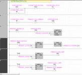
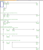
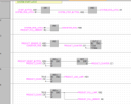
Attached are the 3 ways to program in GXWorks2, Ladder in GXDeveloper compatible mode, Ladder & FBD.


Thanks for your input Parky, I will look into them as soon as I can. Yes I was told that this is the way we had to do it in Lab on Friday. I am in Lab every second Friday working on two PLCs, a Mitsubishi FX and I think the other one is a Siemens. I knew we had 4 exercises coming up but I honestly thought day 1 would start off as a tutorial an introduction to GX works 2 but as I was learning (the readPLC/writePLC/compile/etc,) the engineers in my class were flying through exercises. I think my diagram above is complete now but I cannot test it until Friday week. But I cannot learn it unless someone can confirm if it’s correct. It looks correct to me but I’m a beginner and my lecturer asked me to try complete the exercise and take out the original reset rung, it was something to do with either the way a proximity sensor works or have to use Y2 as true before reset. Therefore I came up with the M3 which made me look stupid I guess, lol. Then he said there was something missing, but what? The end block? If it was just the end block I will be very upset with him. Do you think my ladder diagram above will fail on Friday week?
Last edited:
Sorry Parky, I should have looked at your attachments first, I see you are using a typo of block diagram which I’m not familiar with. I will study this now and I believe further on in the course we will be learning this. Thank you very much
I did a very quick simulation and it worked as expected without problems.
There is one possibility. that it may be possible of a double kick on the product sensor in the real world, I tend to put a slight delay timer on the sensor so it is fully covered before it triggers the count. i.e.
A X3 T1 K2 (200ms)
then use the timer contact to drive the counter.
Yes I assume you will get applications to use FBD (Function block diagram) and Structured text ( more like basic or Pascal).
One thing to remember about FBD type programming you can use local variables within a block of code that are not exposed to the global program. Also timers/counter function blocks do not use actual in-built timers
They use other compiled code so there is no reference to in-built timer/counters.
Something you need to get your head around is the use of globals & locals, structured programming of blocks & Functions or function blocks.
Last edited:
Ok, that’s great, maybe my lecturer knows this and wants to explain it to the entire class at once Friday week as a problem solving lesson. It’s very daunting for me because the mechanical engineer who sits next to me (returning to do year 2 of an engineering course because it’s the first recognized automation/robotics engineering course in the west of Ireland,) and one or two of the other engineers completed this by the end of day 1. I’m not upset about it, I actually want to catch up with them and learn and not slow the class down for everyone. Thanks Parky. I think I’m done with this exercise now, but I’ll draw another separate diagram and enter the time delay. Thanks again.
Last edited:
AsGreenAsGrass
Member
*edit* One thing about the above attachment is the fact you're using M2 that's not designated in the assignment outline for inputs/outputs. if that's not a problem then no biggie
heres my two cents which might not be 100% correct either but heres a shot: *edit*
'when s1 is off both lamps are off' its a momentary push button though lol...This assignment is either worded very poorly or i'm losing it. Heres how i assume it wants to run?
hit start - belt starts - sensor counts - Lamp1 stays on the whole time - 5 products pass the sensor Lamp1 goes out Lamp2 comes on and Belt stops. - you cant hit start until you reset your count - once you reset your count Lamp2 goes out and your back to step 1.
IF thats the case then go
rung 1 stop - start (motor branched around this) - Lamp2 (Normally closed) - M1 output
Rung 2 Sensor- Counter up
Rung 3 M1 (normally Open) - NOT EQUAL command (Counter vs 5) - Lamp1 output
Rung 4 EQUAL command - Lamp2 output (add your stop contact if you want to shut off)
Rung 5 X4 (reset) - COUNTER RESET
One thing about the above attachment is the fact you're using M2 that's not designated in the assignment outline for inputs/outputs. if that's not a problem then no biggie.
it really depends on what they mean by the statement 'when s1 is off both lamps are off'
if say you wanted both lights off when your stop button was pressed you can add the stop to your Lamp2 rung and itll be off until you release your stop.
Tried to do it in the flow of the assignment and as simple as possible, definitely can be more neat with things such as adding belt contacts to your sensor rung etc
Last edited:
M2 is not required as stated in my last post just use the output, as you correctly pointed out the lamps should be off when stopped instead of "TRUE" contact on the lamp outputs just put the System run bit in instead.
It does state that both lamps should be off if S1 is off, however, it is a momentary button (or you would not need a stop button), so the statement is not correct. He should state the lamps are off if the system is in stop/not running. I have come across text in many a specification where the description does not tie in with the proposed operation, this is usually a typo or poor understanding of how a combination of logic can work, and all this coming from highly skilled people so it is not surprising that many projects/ assignments falter.
My step daughter is currently taking a University degree and on one report she did the feedback from the lecturer contained many spelling mistakes and poor vocabulary I wonder how they manged to get their own degree.
By the way, I do not consider myself expertly versed in English vocabulary or spelling but from what I have seen in the last few years the standards are slipping.
AsGreenAsGrass
Member
Yeah, it would be worth asking your professor what he is looking for. Like i said in the previous text he may not like the fact you're adding extra bits to make it more fluent like the 'system run' and the 'pause' outputs although they may make sense to you, the assignment didnt ask for it.
-Considering its a beginners course you shouldn't have to speculate on any of the instructions given.
-When I had questions about a certain assignment I would reiterate the task back to my instructor the way I interpreted it and if he agreed with it, it made writing the logic a lot easier.
-Another thing, take a breather when you get stuck with writing your logic, it does miracles.
Thanks for your input, I guess he meant when stop is pressed (Machine stops) both lamps should be off. I emailed him and he said that my diagram was correct but just to insert the condition M1 in series with both the high and low lamps to ensure that these lamps can only be turned on if the system has started. I don’t know if he meant to bring a pause button M2 into the diagram but one of the students in class may have suggested it as a condition because we had a brief discussion about the m/c pausing when 5 items have accumulated. So my lecturer told us verbally last Friday that we should put it in. I guess my next attachment is the completed exercise minus the timer delay (should he bring up the need for a timer delay on Friday week at least I will understand why.) Thanks guys for all your help, anything else ye might want to add is greatly appreciated

Similar Topics
Hi, I’m looking for a free software (if possible I’d like it similar to GX Works 2.) Has anybody got any suggestions? I’m in college part time...
- Replies
- 2
- Views
- 1,829
Hey I am looking for an active member that has some time to help explain a little bit more about the RS logix program. I failed last semester due...
- Replies
- 6
- Views
- 2,350
Right now I'm in a program for industrial instrumentation and controls. I'm not new to working in the industrial field, but I would really like to...
- Replies
- 12
- Views
- 3,149
Hi everyone,
I have to complete this exercise using LADSIM:
http://www.plctalk.net/qanda/showthread.php?t=80080&page=4
This is how it is...
- Replies
- 40
- Views
- 7,550
Hi everyone,
I have started on a questIon involving a bottling plant using LADSIM.
However, so far, I can only fill one bottle.
I am...
- Replies
- 40
- Views
- 12,692


