Ethernet/IP using RSLogix 500 on a SLC 5/05 to a Servo Controller

timryder

Member
Join Date
Feb 2007
Location
Macomb MI
Posts
176
Ok,

So I have a controller from a company called "Aerotech". I purchased an upgrade to allow the controller to communicate via Ethernet/IP. It's for a project i'm working on. I also had to upgrade my 5/05 to firmware 10 in order for the EIP tools to be enabled in RSLogix 500. SO what I want to do is send a message (Ultimately a string of Ascii data) through EIP to this Servo Controller. I have never used Ethernet/IP before and am totally at a loss for where to begin...

Can anyone help me set this whole thing up? I'm in DESPERATE need of help!

Thanks in advance

Tim
 
Why wont this work here? I have tried so many different methods but it never enables... what I am doing wrong?

| ___EEM__________________ |
| | | |
| I:2/4 |control block N7:10| |
|----] [--------------------------|control block length 58|-|
| |________________________| | | |
| |

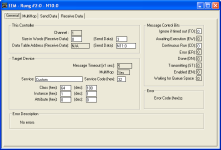
Within my setup screen I have the following settings

______________________________________________________________
THIS CONTROLLER:
Channel: 1
Size in words (Received Data): 0 (Send Data): 2
Data Table Address (Received): 0 (Send Data): N7:20
______________________________________________________________
 
If you put ladder tags around your diagrams (or select the diagram and click the contact looking thing on the toolbar) the spacing will be preserved.

Let me start this by saying I haven't used an SLC in so long that my software doesn't even mention and EEM instruction. So take my advice for what it's worth.

It seems a bit odd to me that you have your control block starting address as N7:10 but are reading from N7:20 for your send data. From what I can tell it looks like your control block is 58 words long. That means N7:10 - N7:68 are off limits. While reading shouldn't be an issue it leads me to believe you may be accessing that block in other locations.

Keith
 
OK so for now I figured out what the heck I did wrong and it was stupid as usual! I didn't enable the SBR instruction to that sub routine... BUT, i'm still having another issue, I have setup my EEM instruction on my ladder with a N.O. push button instruction in front of it and I am having issues when I push that button. I always get an error d8 (Connection was broken) in my EEM instruction... I doubled/triple checked the IP address of the device I am trying to send data to and it's correct. The documentation of this device tells me I need to write data starting at register 300 so within my Setup Screen of the EEM instruction I have N7:10 register (which is = 300) for my "Data Table Address" Field, and I have the recommended settings in the "Service Code" , "Class" , "Instance" fields. I also did a len calculation to get the value in words of my data I wish to transmit so I know i'm sending the right amount of data to the device also.... any reason why I should be getting this error?
 
Ok so now im getting this error which says
"Connection not completed before the user specified timeout".

So what I'm seeing is that it isn't establishing a good connection or transmitting the data before the thing times out...

HELP! why can't my 5/05 talk to it?
 
What service are you using? I was recently working on some TCP/IP stuff using MSG blocks. only thing I had to enter was the correct instance. the correct size, and multihop IP address. I was using write assembly Generic CIP which is what an EEM is if I recall.
 
Please be clearer in the device information and the "recommended settings"; it might make a difference. Post a screenshot, or the *.RSS file, if you can.

Error code 0xD7 and 0xD8 are ordinary Ethernet error codes, not specific to the EEM instruction. The pretty clearly indicate that the target device isn't responding to a TCP connection request at all.

Is this the interface you are talking about on the Aerotech unit ?

http://www.aerotech.com/soloist/ethernetIP.cfm

Aerotech1.png
 
Wow, you guys are good,

Ok so I am using an EEM instruction trying to send some integer registers to the Aerotech Device known as the Ensemble MP running their Ethernet/IP module which I have programmed to allow me access to their integer registers 300-499 and they have 32 bit registers. So that screen cap you posted is the setup screen for the EEM instruction within RSLogix 500 and I have those parameters I've noted earlier set to their respective fields within that setup screen.

So if I'm reading your last post correctly, you would venture to say that the device is either not in a state capable of communicating or perhaps I have a setting wrong in my EEM instruction? Aerotech provided a small help file and this is what they indcated my settings should be for RSLogix 5000 but again im using 500, but they should still correlate no?

///Aerotech Help Document///

EtherNet/IP request to write the values 512 and 1024 to IntegerRegisters(255) and (256):
Service: 0x35 (Write_Multiple_Registers)
Class: 0x65 (Register Interface Object)
Instance: 0x01 (Instance 1 maps to Integer Registers)
Request Data (Start Register Number, End Register Number, Register Values): 0xFF, 0x00, 0x00, 0x00, 0x00, 0x01, 0x00, 0x00, 0x00, 0x02, 0x00, 0x00, 0x00, 0x04, 0x00, 0x00
Response Data: (Status Code): 0x00, 0x00, 0x00, 0x00

///End Aerotech Help Document///

So within my Setup screen I have set those values I can see clearly correspond like Service, Class, Instance and I think it should all be correct within my ladder.....


| __EEM________________________
| I:2/4 | |
|---] [--------| control block: N7:10 |--
| | control block length: 58 |
| |_____________________________|
|


So at this point I'm not sure what I'm doing wrong...
 
Last edited:
The Aerotech example looks like it is passing double integers. It is using 16 bytes to pass 4 values and the byte groupings come up correctly if looked at as double integers. So you may need to put some dummy spaces in your data group to get the byte alignment right and you may need to double your word count. Also, I'm not sure how it handles a single word but I assume the start and end addresses would be the same.

So, directly from the example:

///Aerotech Help Document///

EtherNet/IP request to write the values 512 and 1024 to IntegerRegisters(255) and (256):
Service: 0x35 (Write_Multiple_Registers)
Class: 0x65 (Register Interface Object)
Instance: 0x01 (Instance 1 maps to Integer Registers)
Request Data (Start Register Number, End Register Number, Register Values): 0xFF, 0x00, 0x00, 0x00, 0x00, 0x01, 0x00, 0x00, 0x00, 0x02, 0x00, 0x00, 0x00, 0x04, 0x00, 0x00
Response Data: (Status Code): 0x00, 0x00, 0x00, 0x00

///End Aerotech Help Document///

assuming your send data starts at N12:0 the data would be:

N12:0 255
N12:1 0
N12:2 256
N12:3 0
N12:4 512
N12:5 0
N12:6 1024
N12:7 0

and you would need to send 8 words.

If you only wanted to send 512 to register 255 I THINK the transfer would be:


N12:0 255
N12:1 0
N12:2 255
N12:3 0
N12:4 512
N12:5 0

and the word length would be 6.

But just guessing.

Keith
 
Ok so that will help me when I actually get these dumb things talking,

any thoughts as to why I keep getting a timeout? The ladder does Enable the EEM instruction when I push my button so I know that it HAS sent out the packet to establish a communication link but it never gets a response to verify that something is on the other end, so after the programmed timeout I get the error which says "Failed to get a response before programmed timeout" in my EEM instruction Status...

Quick Rundown of what I have check already
Subnet: Same
IP Range: Same
Gateways: Same
Test connection to Aerotech through Their Software: Works and talks fine
Make sure program runnnig on Aerotech Controller: Checked and is running
Try a MSG instruction: Tried it, same result
Test physical Ethernet Cable: Did, tested fine
Ping Aerotech: Pings with under 22ms response time


In the Aerotech software, I have the ability to monitor their memory registers and I am looking at them all the time to see if my data gets there. I still am getting the communications timeout. Should I be talking to Aerotech you guys think? Would it be more likely that it is their issue and not the SLC 5/05? Can Channel 1 be used simultaneously for programming and EEM instruction communications?
:mad:
 
Are you sure that the Aerotech device will respond to an incorrectly formatted message? Some devices will respond and tell you what you are doing wrong. Some just won't respond at all.

You can use the Ethernet port for anything you want as long as you stay inside its connection capability. One EEM and a programming connection won't be a problem.

Keith
 

Similar Topics

So I have an ABB ACS880 drive with a built in ethernet module, the FENA011. I'm using a Controllogix processor to control it via the ethernet...
Replies
6
Views
3,797
Hello all, I have gained much from browsing the forum over the years. I am an industrial electrician which at our factory which means anything...
Replies
2
Views
3,870
hi guys can any one help me with correct procedure to connect RSlogix5k to logix5561 plc step by step. i am using ENET ethernet module. 1. can...
Replies
2
Views
5,377
Studio 5000 & PF 525, Ethernet Comms, Encoder FB, Using Motor RPM as speed reference I'm trying to figure out how to send a speed reference in...
Replies
6
Views
933
Hi All I have connected a Keyence SR1000 to a Compact Logix PLC and am triggering the scanner and reading barcodes over Ethernet/IP, no issues...
Replies
2
Views
837
Back
Top Bottom