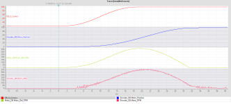
S-Curve Profile for Motor Control Project

It looks to me like the OP is trying to use a filter of some kind as a target generator. There is no constant velocity section. Also, s-curve is not symmetrical so the OP must be trying to use some sort of filter or filters

But drbitboy DMD is on the job extracting teeth.
Time for more pop corn.
 
However, it doesn't fully perform the s-curve movement, it responds late to the position and settles late. What kind of inference can I make from this?

https://ibb.co/n076XsW


That the speed PID is doing exactly what you told it to do.

it responds late and settles late
A PID drives error (PV-SP or SP-PV) to zero, so a PID will react to non-zero error and will not react to zero error. The PID will not move the CV until after it detects error, and since you are modifying the SP with an S-curve, that error starts at zero and increases very slowly, which means the change in CV also starts at zero and increases very slowly, and only after (i.e. "late" with respect to) the non-zero error is detected.

So yes, the PID is doing exactly what you told it to do.
 
#ERR := #SET_Position - #Motor_Position;
#INTEGRAL_TOT := #INTEGRAL_TOT + (#T * (#PRV_ERR + #ERR) / 2.00);

IF #INTEGRAL_TOT > #AWU_LIMIT THEN
#INTEGRAL_TOT := #AWU_LIMIT;
END_IF;
IF #INTEGRAL_TOT < (- #AWU_LIMIT) THEN
#INTEGRAL_TOT := (- #AWU_LIMIT);
END_IF;

#Result_RPM := ((#KP * #ERR) + (#KI * #INTEGRAL_TOT) + (#KD * (#ERR - #PRV_ERR) / #T));

#PRV_ERR := #ERR;

IF #Result_RPM > #HIGH_LIMIT THEN
#Result_RPM := #HIGH_LIMIT;
#OUT := #Result_RPM;
ELSIF #Result_RPM < #LOW_LIMIT THEN
#Result_RPM := #LOW_LIMIT;
#OUT := #Result_RPM;
ELSE
#OUT := #Result_RPM;
END_IF;
------------------------------------------------------
Values :
AWU_LIMIT Real 4000.0
KP Real 1.0
KD Real 0.01
KI Real 0.8
HIGH_LIMIT Real 600.0
LOW_LIMIT Real 0.0
T Real 0.1

That is my PID code. The PID function block operates within a 100ms cyclic interrupt.
 
That the speed PID is doing exactly what you told it to do.


A PID drives error (PV-SP or SP-PV) to zero, so a PID will react to non-zero error and will not react to zero error. The PID will not move the CV until after it detects error, and since you are modifying the SP with an S-curve, that error starts at zero and increases very slowly, which means the change in CV also starts at zero and increases very slowly, and only after (i.e. "late" with respect to) the non-zero error is detected.

So yes, the PID is doing exactly what you told it to do.

Yes, it responds late and settles late. However, there is also an error in the value it settles at. I want to correct that. If the desired position in the S-Curve is 100, my motor should complete its movement close to 100
 
Can the position PID send a negative value of the SP to the speed PID?

If the position PID does send a negative value of the SP to the speed PID, will the speed PID see the negative value, or does the speed PID clamp negative SP values to 0 (zero)?

...
Code:
[B]
[I][COLOR=#ff0000] ELSIF #Result_RPM < #LOW_LIMIT THEN[/COLOR][/I][/B]
   #Result_RPM [B][I][COLOR=#ff0000]:= #LOW_LIMIT;[/COLOR][/I][/B]
   #OUT := #Result_RPM;
------------------------------------------------------
Values :
LOW_LIMIT    Real    [B][I][COLOR=#ff0000]0.0[/COLOR][/I][/B]
...
That is my PID code. ...

Called that one, didn't I? And before @Peter even had the popcorn made ;).

So how did I (as well as a few dozen others watching this soap opera) know that? Look at the PID equation. Think about what it is doing. Differential equations and Laplace transforms are nice for going deeper, but they are not necessary to understand what this dead-nuts simple, linear algorithm called PID* (cf. here) is doing.

You wrote the code: do you not understand what you wrote; can you not simulate the discrete, cyclic 10Hz, closed-loop (motor plus PID) system in your head?

Those are not rhetorical questions; neither am I mocking you, though I will unabashedly own my bluntness. I would prefer you figure this out on your own, because that is how you, and not chatGPT, will know it for the rest of your life.

The trick to programming PLCs is not figuring out what you want the PLC to do. The trick to programming PLCs is figuring out how to tell the PLC to do what you want it to do.

* actually PI only, most likely

Hint #1: try calculating and tracing (trending, plotting) the error (#ERR).
 
...If the desired position in the S-Curve is 100, my motor should complete its movement close to 100


Then maybe you should try telling it to do that.

Hint #2: have you told it to do that in any of these previous attempts? Don't think hard about it, there is only one correct and obvious answer.
 
I'm too d**b to be able to do this :(
I find this hard to believe.

You coded the PID instruction in Structured Text, you even included a weak form of anti-windup reset. You coded an S-curve, so I suspect that you understand basic algebra and math.

The PLC cares not a whit what you want it to do, but it will mercilessly and inexorably do exactly what you tell it to do. That can be intimidating, but it is also very liberating, because when the PLC does not do what you expect, you know the problem is in one or both of two places: your expectations; the code you wrote. And you have dictatorial control over both.
 
I don't understand why at 20 seconds, the REF_ERPM is at its peak but target position, DB_S curve_x, is not changing.
DB_S is the SP, and the S-curve profile, which is driving the SP, has reached its end point, which is why it, and SP, are constant.

There is a huge phase delay between the db_S curve_x.
OP is minimizing position error magnitude |SP-PV| by varying velocity. Yeah, ouch.
Also the ending of the Motor_ref_PRM is not smooth.
I know it goes against procedure, but see the ELSIF clause in Post #19.

I am pretty sure there was some overshoot, which could not be eliminated because the PID cannot command a negative velocity, but maybe not (perhaps TD is large enough?).
 
There is nothing like re-inventing the out of round wheel. Norm Dziedizic posted how to generate a 7th order motion profile to go point to point years ago on this forum. The motion profile would be symmetrical and the velocity, acceleration AND jerk would be 0 at the beginning and ending points. Polynomials are easy to differentiate to get the velocity, accelerations and jerk as a function of time too. These can be used for feed forwards. Feed forwards will eliminate most following error.

I didn't get a chance to eat much pop corn on this one. :(
 

Similar Topics

Hi The pump smart PS220 VFD has the ability to estimate pump flow based of pump characteristics and measured motor data. The calculations...
Replies
12
Views
3,743
Hello all, I need to write a code for S-curve motion profiles (7 segments) to control speed of motor via PLC. however, I cannot find the...
Replies
76
Views
17,625
Does anyone know of an Add-On Inst. or PAX Block that can be used to develop a characteristic curve? I have a Variable Speed Pump with a Current...
Replies
13
Views
2,643
Hello Forum, I am developing a Pump Control System and one of the most important modes of operation, is to keep the Pump operating inside it's...
Replies
36
Views
14,981
How can I make a powerflex 750 follow a curve like this? Doesn't have to be this exact curve, just something similar.
Replies
7
Views
2,347
Back
Top Bottom