Hey guys,
Looking for a nice resource for some CAD symbols for when I do electrical drawings.
I stumbled across this one a few years back and it's really good! But I'm looking for a nice way to illustrate some analog devices connecting to Turck Fieldbus IO and I'm just drawing a blank of how to show it.
https://symbols.radicasoftware.com/index.php
A machine we're building will have several Linear Transducers for positioning of Hydraulic Linear Motions and Analog Pressure Switches. I have Turck analog fieldbus IO mounted on the frame but no clue how to draw the devices plugging into it.
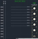
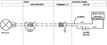
Anyone have any reference images or files they care to share when drawing this type of situation? Here is what I have so far (attached).


