SLC 5/04 OSR question

JHarbin

Member
Join Date
Sep 2009
Location
NC
Posts
909
I'm looking at an offline copy of a program that has these two rungs, in this order (see attachment).

B3:16/3 is a OSR in the first rung and an OTE in the second rung – what is the status of B3:16/3 and B3:16/4 when I:1/12 is TRUE?

B3:16/4 is used as a "one-shot pulse" elsewhere in the program, B3:16/3 is only used where shown in the attachment.

OSR Rungs.png
 
It looks to me like rung 5 is a simple one shot reset B3:16.3 is the one shot status bit. Bit B3:16.4 is the reset bit it will be true for just 1 scan of the ladder program when I:1.12 goes from False to True
Rung 6 will do nothing because when I:1.12 is true it will set B3:16.3 to true. Because B3:16.3 is already true in rung 5 (ocr status bit)
It’s beyond me why somebody would program it this way OCR bits should be used only one time in any program if used more than once they can cause unwanted / unexplained results.
 
Huh, took me a few double take to realize they reused the one-shot in another rung. Agreed, you can remove rung 6 and nothing would change. Very confusing.
 
To me it looks like someone was used to writing his own OneShots on a PLC that didn't have them. In this example if you changed the OSR to XIO followed by line 6 you would have your own OneShot.


Probably just force of habit for the programmer, as line 6 is doing nothing as the bit would already be on.

I thought the same, but OSRs are used normally through out the rest of the program. I wonder if the programmer thought this would ensure that it was "really-really" one-shot.

I be interested to know how the PLC actually handles the logic, though.
 
Once the OSR bit goes high it will stay high until the input drops. Line 6 only turns it on, but it's already on.

But don't add an AFI or XIC Always Off on line 6 because then line 6 would turn off the OSR bit and it would trigger every scan because it would be off when line 5 is scanned again.

Is this the only OSR written like this in the program, or are there others similar?
 
From the RSLogix 500 Instruction Set Help

"You must enter a bit address for the OSR. Use either a binary file or integer file address. The bit address you use must be unique. Do not use it elsewhere in the program"
 
Once the OSR bit goes high it will stay high until the input drops. Line 6 only turns it on, but it's already on.

But don't add an AFI or XIC Always Off on line 6 because then line 6 would turn off the OSR bit and it would trigger every scan because it would be off when line 5 is scanned again.

Is this the only OSR written like this in the program, or are there others similar?

This is the only one written like this.

It really isn't a big deal, I'm replacing the PLC with another brand and the logic will be changed - I was just trying to get inside the head of the programmer to see why it was done that way, and only in this case.
 
naturally there's more to this story ...

my advice is that you do NOT remove or otherwise alter the "weird" rung that's causing so much confusion ... here's why ...

everything that's been posted so far is assuming that the system will always be used in "normal day-to-day" operation ...

but ...

the original programmer was apparently making use of the Allen-Bradley "PRESCAN" operation to handle certain "Go-To-Run" situations ... (including a possible power failure - and a subsequent return of the power) ...

here's how to get a better understanding of what you're looking at ...

suppose that we enter a new temporary "test" rung and then go through a few experiments ... (WARNING! ... naturally it would be safest to do this with a lab setup – rather than with the company's production equipment) ...

the "test" rung should be located BELOW the two rungs that you've already posted ...

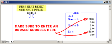
the new test rung should consist of an XIC instruction – with the address B3:16/4 – which is the bit address documented as "NESS HEAT RESET ONE-SHOT PULSE" in your existing code ...

the rung should also include an ADD instruction ... resist the temptation to use a CTU (Counter) instruction instead ... you'll get much more reliable results from the test by using a simple ADD instruction ... for Source A – and for the Destination entries of the ADD instruction – use a previously UNUSED Float location ... I'm using F8:0 for my example – but MAKE SURE that the address that you enter has NOT been used elsewhere in your entire code ... for Source B of the ADD instruction just enter the value of 1 ...

now to execute the experiment ...

as you flip the field input back and forth – your input signal I:1/12 (documented as HEAT SWITCH OFF POSITION) should cycle between "green on the screen" – and NOT "green on the screen" ... and the value shown at the Destination of your ADD instruction should INCREMENT by 1 each time the switch's XIC instruction highlights as green ...

this indicates "normal" day-to-day operation of the code that you posted ... in simple terms, the OSR is "firing" for one scan each time the field input passes electrical current ... this is what has been discussed so far in your thread ...

now let's go deeper ...

leave your field input signal I:1/12 in whatever position you need to give you a "green on the screen" highlight ... now cycle the SLC processor several times between the Program mode and the Run mode ... you can do this either with the keyswitch – or remotely by using the keyboard of your computer ... you should see the value shown at the Destination of your ADD instruction INCREMENT by 1 each time the processor goes into the Run mode ...

now let's go even deeper ...

completely remove (DELETE) the rung shown as Rung number 0006 in your original post ... specifically, get that "confusing" rung completely OUT of your code ... do NOT simply "disable" the rung in any way ... you can reinsert the rung once the testing is finished ...

now here's the kicker ...

once again - leave your field input signal I:1/12 in whatever position you need to give you a "green on the screen" highlight ... now again - cycle the SLC processor several times between the Program mode and the Run mode ...

this time, the value shown at the Destination of your ADD instruction will NOT increment each time the processor goes into the Run mode ...

ding – ding – ding ...

note that the results of a "Go-To-Run" event will be DIFFERENT once the "confusing" rung has been removed ...

so ...

I'd be willing to bet some SERIOUS money that your original programmer was making use of Allen-Bradley's little-known PRESCAN feature to insure that whatever "stuff" is being controlled by that B3:16/4 bit (NESS HEAT RESET ONE-SHOT PULSE) in OTHER places in your existing code – actually gets executed whenever the processor first goes into the Run mode – without having to manually recycle the field input device for bit I:1/12 ...

TIP: there are different – and probably better – ways to achieve the same results – and frankly I think that the original programmer should have included more documentation about what he was trying to accomplish ...

hope this helps ... party on ...
.
TEST_OSR.PNG
 
Last edited:
from your Post #8 ...

It really isn't a big deal, I'm replacing the PLC with another brand and the logic will be changed - I was just trying to get inside the head of the programmer to see why it was done that way, and only in this case.

no offense intended to anyone - but many (most?) programmers only worry about making the machinery work properly in normal "day-to-day" operation ...

but - there's another level of programming which considers unexpected power failures - and many other BEYOND normal "day-to-day" operation situations ...

some of those dogs don't bark until AFTER they bite ...

your efforts to understand "WHY?" are a good sign that you're interested in learning and progressing to a higher level ...

best of luck with your project ...
 

Similar Topics

Hey guys! Ok, now I'm dealing with a SLC 5/03 processor. Here's the pic. The thing is I was programming some stuff and when I tried to...
Replies
17
Views
6,641
I have a program (written by others) at a customer of ours, which is using a poor mans shift register as a method of tracking items on a long...
Replies
11
Views
5,604
I can;t seem to make the osr bit work correctly on a slc 5/04. I have a analog 0-10 volt input which reads a speed pot mounted to the...
Replies
17
Views
4,880
I’m attempting to send a temperature from a SLC-5/02 to an EZiMarquee display. The vendor said to use a MSG instruction to send the data to the...
Replies
1
Views
55
Hello all. I have a few SLCs in my plant and of late we've seen a weird issue: The system will be running normally and then randomly the outputs...
Replies
2
Views
70
Back
Top Bottom