Components that allow you to see the state of individual EStops, Safteys, etc..

jds8086

Member
Join Date
Jan 2020
Location
Kansas
Posts
42
In my current place of work, some of our lines have a lot of E-Stops and safety devices scattered around and if one of them acts up or we have a wiring issue, it's a real pain in rear to find the culprit. I'm assuming that there are accepted methods/devices out there that will allow you to see the state of these devices individually so that you have a place to start when troubleshooting and if so i would appreciate a nudge in the right direction. We use Allen Bradley control products.
 
It's called auxiliary contacts and digital IO. It's not great, but it's one way to know which exactly was pressed.

I'd imagine there will be some sort of safety rated emergency stop button that is on a network, but it would likely require a safety rated PLC that "spoke" that protocol.
 
A safety PLC, or at least a programmable safety relay will give you a lot of info/feedback, with a safety PLC you can even show all that info in an HMI for easy(ier) troubleshooting.
 
If there is a wiring issue, not just finding which button is pressed; I start doing a resistance check on the estop string with the power off. Check from S11 to last device in string (need wiring diagram). Continue working back up the string until you find that you have continuity. Whichever device is after the last one with continuity is where you will find the wiring issue.
 
I'm guessing you've got a bunch of e-stops in series rather than individually wired to safety relays/inputs. Lots of not-so-fond memories troubleshooting intermittent wiring issues in such setups...

Networked devices are probably the best solution imo (if feasible). You can also have each safety device tied to its separate relay (or to separate inputs on a safety PLC) but that gets expensive fast.

Auxiliary contacts will tell you if eg an e-stop was actually pressed, but on a large systems you'll end up eating a lot of inputs and it won't help with a wiring issue.

The most robust system I have ever seen in terms of pinpointing errors in the e-stop circuit was an old machine that took a wires to inputs directly off of the safety circuit in between each e-stop.

If there is a wiring issue, not just finding which button is pressed; I start doing a resistance check on the estop string with the power off. Check from S11 to last device in string (need wiring diagram). Continue working back up the string until you find that you have continuity. Whichever device is after the last one with continuity is where you will find the wiring issue.
This assumes you have a complete break in continuity. The ones difficult to troubleshoot are where you lose continuity just long enough to trip the circuit but immediately thereafter regain it.
 
So, theres a few things to do with this.

If there is no upgrade in the works, the best way to lay out a safety system short of running everything back to IO (which we literally just did), is to have specific terminal blocks laid out in a cabinet making it easy to check where the safety chain is broken.

The safety circuit gets laid out in a long series so if anything is broken it can stop the system just the same. The idea is, every single device has both its wires run back to the main cabinet, as opposed to running from one device to another. even if the two devices are right next to each other you run those wires back to the main cabinet.

When you run those back to the main cabinet, it would look like this

Main power -||- out to Device 1
In from Device 1 -||- out to Device 2
In from Device 2 -||- out to Device 3
In from Device 3 -||- MCR

When you lay it out like this, all it takes is running a meter down a terminal strip and where the power is broken, you know which device is not functioning.


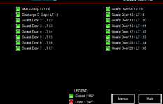
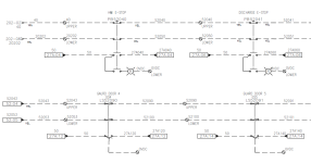
The New way to do it is to install safety devices that have a NC and a NO contact inside, the NC contact stays for the E-stop, but the NO is now used for a PLC input to show which device is going to be open/bad. I'll be going out to a site to download an updated program for this exact type of safety layout in a week or so. and my updated Panelview program will have a page dedicated to showing door and safety status so anyone can click on it and see what is open and what isn't.


safety.PNG
safety2.PNG


The newest way I've seen is to use ASi network safety devices.... they are individually addressed devices on a two wire node network that can activate a safety relay and also give feedback at the same time with minimal wiring. Unfortunately these are harder for regular Joe to integrate and more expensive upfront, but they look solid (never used them).

https://new.abb.com/low-voltage/products/safety-products/as-i-safety
 
Last edited:
Apart from those things mentioned, If you have a safety device with some sort of indicator that goes a long way.

It should be common practice, for example, to use a lighted E-stop pushbutton that lights when it is pushed in. This could be a simple swap of LED and contact blocks if you are using something like the 800 series Allen Bradley pushbuttons.

For another example, Banner makes a great E-stop that has a lit base when pressed in:
https://www.bannerengineering.com/my/en/products/part.26266.html

In this example if you are looking at a conveyor line full of E-stops and you can just glance and see which light is flashing, that can make your life much easier.

As mentioned with others - run every safety device in the PLC. Don't use it for safety - but do use it to indicate if a safety device is active.
 

Similar Topics

Hello everyone, I am working in a platform and we installed FTV CLIENT SE V 12 IN ALL THE CLIENTS COMPUTERS, we have 6 clients and only 1 is not...
Replies
0
Views
96
Hello everyone, I'm having issues with connected components. I got a new laptop and I installed all the RA programs I need without problem. I was...
Replies
1
Views
274
Connected Components Help Hi there everyone, I’m recently new to the PLC world and was hoping somebody might steer me in the right...
Replies
3
Views
419
was trying to use Connected Components to connect to a 525 drive via usb with the face off but can't seem to connect to it. the screen lights up...
Replies
7
Views
763
So I'm using CCW to program a panel view and this is not my first I have done many. My Problem is I get an error message that I have never seen...
Replies
2
Views
481
Back
Top Bottom