VFD Not Consistently Ramping down

I had to get an old shot blast cabinet working that had a jet wheel and a turntable inside.


At first I wondered why the jet wheel had a reversing contactor, and a couple of timers connected to it.


Turns out when you stop the motor it timed 1/4 second then plugged the motor (still going full speed) in reverse for 3/4 second. You could hear that out in the parking lot and see the entire machine jump. Not something a controls engineer would design on purpose in my mind. Plus it still took a couple minutes for the wheel to stop.


When I work on presses I now make sure the anti-plugging system works properly.
 
Believe it or not, that was very common back 'in the day'.

We sold a lot of Dynamic Motor Brakes for Wheelabrator and other blast machines as well as high speed shapers and such 'Back in the day'. They were much safer, efficient and controllable than Plug Braking.

The function was that when the motor starter opened, wait 150-300ms for the field to collapse, then turn on SCR's to inject DC at a controlled current level. They either went for a time setting, or by sensing a stop from an idle phase (a pulse in the generated back emf).

They worked very well, but have mostly been replaced by VFD's with either DB Resistors, DC Injection Braking, or Regen ability.

The downside to Plugging, or DC Injection is (of course) the energy is dumped into the motor, and can cause overheating and damage, depending on the duty cycle. With the other forms of braking (via vfd's), the energy is mostly removed from the motor and dissipated externally.
 
Yep - Wheelabrator, remember that name now.


No rectifiers or resistors, just reverse 480V 3 phase into the motor running full speed. I was surprised he motor didn't rip off it's mounts - or rip the base off the motor. Or just explode.
 
I agree Plug Reverse stopping was very common back in the old days (Not that long ago)
I have worked on many of them mostly on steel mills
if they are not setup correctly you can damage the motor I Rember seeing one shear the motor shaft because the timing was set wrong as stated overheating is a common problem with plug stopping and DC Injection
Motor breaking is more difficult and tricky then starting the motor you must engineer it carefully
As a side note I once had a call for 200HP submersible water pump that about once a month would shear the motor shaft. it was discovered the discharge was 24" dia over 200" vertical lift with no check valve. when the pump stopped it drain back into the sump motor would spin in reverse. if it tried to restart while free spinning in reverse it would shear the shaft as simple restart delay timer solver the problem
 
Yea, the old motors were tough as nails compared to the currently available high efficiency (read optimized = no extra material) motors today. I like to think of it like an old big block cast iron engine vs. an aluminum turbo'd v6...
 
I like to think of it like an old big block cast iron engine vs. an aluminum turbo'd v6...


Now I miss my old Chrysler with the police 440 it had......


Too bad the transmission and rear end couldn't handle it and needed both replaced every couple of years, but in retrospect I think it was worth it.
 
A few things to consider.
- (0 V fault). Normally occurs when you turn the hard wired run command off . Out of sequence.
.
- the braking method used to stop the drive needs to be set
You might be telling the drive to coast.
I have not looked at yaskawa for many years.
-
 
I would also join the chorus that you probably need a brake resistor.

If the drive is hitting the DC bus voltage limits while stopping, doesnt the drive indicate that in some way ?
On the VFDs I work with, when the VFD hits the DC voltage limit you get messages on the display as well as in an internal log that can be investigated later. So this can help you diagnose the issue.
 
Jesper: I've not seen an indication like that before on decel, only on accel, when current limit is hit. At least on the brands I've worked with.

It is typically easy enough to see if it's an issue, now that I think about it. What I've done in the past is program the drive to enable the DB transistor, like there was a DB resistor connected, then see if it trips on Over Voltage. The reason this works is because the drive normally *either* uses bus-voltage-regulation (slowing/stopping the decel ramp) *or* turning on the DB (shunt) resistor when the DC Bus is too high.

Ian: When I typed OV fault, I meant Over Voltage (DC Bus)
 
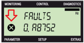
For example on Siemens G120 with a BOP-2 display, if the diagnostics page is selected, it will display warnings, also intermittent warnings such as DC Bus voltage limit.
When the diagnostics page is not selected, there is still a symbol that will flicker on and off (at the arrow in the attached image).
And you can also investigate the error log which will display past DC bus voltage messages if any exist.

Siemens_BOP_diagnostics.png
 

Similar Topics

Hello, first of all let me state for the record that I'm not a tech of any kind, I have limited experience with industrial automation devices, so...
Replies
3
Views
79
Sorry in advance for the long post, but this requires a little back story. I work in a facility with a couple hundred VFDs Most are in a web...
Replies
14
Views
214
Customer want to use contactor for their 5HP motor blower application. im leaning to VFD. anyone use contractor for blower application...
Replies
9
Views
196
Hi, I would like to assemble a simulator/practice booster pump system that uses PID to maintain steady water pressure under various outlet demands...
Replies
0
Views
82
Hello, It is mandatory to use VFD IF i use IE5 electrical motor? What happens If connect it directly as delta without VFD? Please look at motor...
Replies
1
Views
139
Back
Top Bottom