Planning for Troubleshooting

Join Date
Apr 2002
Location
Just a bit northeast of nowhere
Posts
1,117
Hi everyone!


These days, I'm using integer-driven sequencing to run my state logic. My current program is an update on a Micrologix 1200, with RSLogix 500 software.

First, I know RSLogix has a sequencer function, but I'm intentionally trying to develop a method that will apply to as many platforms as possible, and not everybody has a sequencer. I'd rather do the extra work and be consistent :)

The state logic is basic stuff. It's the following concept, applied to AB ladder logic :

if STATE (N7:0) = 2 and I:0/0 = ON, then STATE (N7:0) = 3

Meanwhile, in the output processing ladder :

If N7:0 = 2 then Latch O:0/0
If N7:0 = 3 then Unlatch O:0/0

Pretty simple concept. Here's the problem.

Even a small program has a host of states to it. Now, if I'm a maintenance man trying to trace out the outputs related to a state, I can do a "find" on the integer register, but not the VALUE!

That means I can find every reference to STATE (N7:0), but not the one or two instances where STATE (N7:0) = 2.

That means my maintenance guy is going to be searching the entire output processing ladder for every instance where N7:0 = 2, cursing me at every ladder rung.

I'm not that cruel.

I've considered every way I can think of to simplify this somehow, and make searching more intuitive, but the only thing I can think of is a logical bit for each state, that turns on the outputs. But if I do that, why not just go back to the Latch-Unlatch bit-based sequencing approach?

Now I know there are guys here who use the integer method. If any of you have tackled this issue before, what approach did you use to make the state-output relationship easier to trace?

Thanks!

TM
 
Sounds bad, maybe every comparing for N7:0 variable have to build same Rung (at least sequencer). Not use set (state), use N7:0 +1 incrementation, when every step have true at least 1 scan.
Try collect Outputs to same rung (maybe impossible).
For Output use when N7:0=2 then OTE output, not use latch.

Replace Step-coditions by Compares and shift by ++1 in follow example:
http://www.kolumbus.fi/sepala/WEB/S7-I7215.htm
 
I tried this method once:

Build your sequencer to run your logic, (inputs, outputs), etc.

Build another sequencer to imitate the machine steps.

You can compare words this way and show the guys the step the
program stopped at, write a fault table etc...
 
Thanks for the feedback, Seppo!

>>Not use set (state), use N7:0 +1 incrementation, when every step have true at least 1 scan.<<

If it works like I expect, changes in state will be driven by feedback from the current state, so this should not be an issue.

>>Try collect Outputs to same rung (maybe impossible). <<

I'd considered breaking up my output ladder and putting the outputs into the state routines that control them, and yes, it's a solution, but it seems...inelegant. I'm much attached to the idea of having all my outputs grouped into one place.

>>For Output use when N7:0=2 then OTE output, not use latch. <<

99% of the outputs use OTE anyway. I only use Latch when an output has to remain on for a few states. And I've taken provisions to protect against all the famous "problems" latches create, like "on-at-power-up".

>>Replace Step-coditions by Compares and shift by ++1 in follow example:<<

A bit-shift sequencer, eh? That's a very valid approach, but I want to see if there is a work-around for the integer method.

Again, thanks!

TM
 
Thanks, Mike!

>>I tried this method once:

Build your sequencer to run your logic, (inputs, outputs), etc.

Build another sequencer to imitate the machine steps.

You can compare words this way and show the guys the step the
program stopped at, write a fault table etc...<<

Neat approach, all the tracability and all the benefits of state logic.

I've considered adding another ladder to my program, a sort of "translator". Every state would activate a corresponding bit, which would in turn activate outputs.

Perhaps my pre-conceptions are shooting me in the foot here.

I think the state ladder should include states and state transition logic - nothing else. I handle outputs in a separate ladder.

I am increasingly leaning towards grouping the outputs with the state machine that drives them. It would compartmentalize the logic, making tracing simpler. But I am still loathe to do it, for the reason stated above.

ARRGH! I'm so stubborn, I get on my own nerves!

TM
 
State Machines

The only compromize solution would be to use integer state number and also a decode ( DCD ) instruction to convert the integer state to a bit. This would allow one to do a search on the state bits. It would also allow one the flexibity of integer states. A problem arises when there are more than 16 states. In this case two decode ( DCD )

I use the integer/bit state machine technique on Modicon PLCs. It is easier than AB on large state machines because Modicon has a MBIT function that is not limited to 16 bits. Compares are big and bulky on the Modicon so testing bits is much nicer. I call it the Peter Miles state machine. Peter Miles is a Modicon Application Engineer who taught it to me in Mississauga, CA. Maybe some of you have met him.
 
Instead of using latches use the limit statement this will eliminate the need for your latches. (Latches, we don’t need any stinking Latches!!!!!!!!!!!)

LIM 20 N7:50 50-----------------------(B3/0)

Also I usually do not increment (N7:0 +1) I move a value into the register when the state I need is complete, then go to next step using an equal instruction. I use increments of ten just in case something has to be added to sequence or God forbid I missed something. I also group all my outputs with my limits in one area.
 
This will add some memory but instead of comparing to a constant compare to an integer location (N7:20) set equal to zero with the symbol of 'Zero'. Do the same thing for all the possible state numbers (N7:21 = 1, symbol 'One'). The user can search the program for the state based on the symbol and get to the location in the program he/she needs rather quickly.

Also, if you need to keep a state set for at least one scan be a little careful of the order of your state increments. As a matter of course I always try to make my state machine increment and I arrange the state driver rungs in descending order. This guarantees I am in a state for at least one scan. Now if you don't want to be in a state for one scan and you want the highest valid state from that scan enter the state driver rungs in ascending order.

Hope this helps,
Keith
 
Example Ladder State Machine

All State Transition are kept in one area and to one rung for that paticular state.
A nice history is kept, to determine what may have went wrong

State 2 Input X Const 1 State Reg
--| |-------| |-------| A Move B ||
|
|
State 3 Input Y |
--| |-------| |------


State 1 Input z Const 2 State Reg
--| |-------| |-------| A Move B |
|
|
State 3 Input q |
--| |-------| |------


State 1 Input D Const 3 State Reg
--| |-------| |-------| A Move B |
|
|
State 2 |
--| |------|


Const 1 State Reg State 1
---| A EQUAL B |--------------( )


Const 2 State Reg State 2
---| A EQUAL B |--------------( )


Const 3 State Reg State 3
---| A EQUAL B |--------------( )


**** State Change ****

State Reg Last State No Transition
---| A EQUAL B |--------------( )

No Transition State Tran
--|/|------------------------------------( )


State Reg Last State
---| A MOVE B |


*** HISTORY****

State Tran Hist 3 Hist 4
--| |------| A MOVE B |

State Tran Hist 2 Hist 3
--| |------| A MOVE B |


State Tran Hist 1 Hist 2
--| |------| A MOVE B |


State Tran Last State Hist 2
--| |------| A MOVE B |


Made a decision

Yeh, only took all day :p

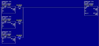
My final state rungs look like below.

EQL tests the current state, B3:0/1 heads off to the output ladder (with all related tracability). I:0/1 represents the combination of feedback needed to move on to the next state, ala MOV.

I was pleasantly suprised that this arrangement did not create "ugly" logic. In fact, I'm quite pleased with the result. It also let me remove my latches from the output ladder, which I was just using to avoid 2-screen-long ladder rungs anyway.

Thanks to everybody for the feedback! You guys are always a life saver.

TM


--I EQL I-----------------------------( B3:0/1)
I I I
I A: N7:0 I I I:0/1
I B: 2 I I------I I-------I MOV I
I I
I A: 3 I
I B: N7:0 I


Timothy, What I do is
a) assign a dedicated binary word to the output ie O:0/1 = B30:1
b) If N7:0 = 2 and output O:0/1 is meant to be on then () B30:1/0
b) If N7:0 = 4 and output O:0/1 is meant to be on then () B30:1/1
etc etc
c) at the end of the routine I then do a NEQ B30:1 to () O:0.1

Hope this makes sense. Regards Alan Case
 
Continuation of above. This method allows you to turn on an output from 16 different locations without 16 branches in your output file and you can also see which binary bit is on quite easily in the NEQ instruction.
A test for the beginners here. Reason NEQ used instead of GRT???

Regards Alan
 
I'm not totally sure what you are looking for but:

you can use a MEQ compare for each output. each will have a unique compare word file address from an array you define to hold them. each of these words can be configured to the 16 inputs states of a 16 point input card which are required for that rung Output. Create similar file words to be use as Mask, where you configure "0" to eliminate comparison of "Don't Care input Conditions". Include as many MEQ in series as you need for conditional logic (Input of Output examination) required for a particular Output. The Source word is address of Card slot.....I:1.0,,,,O:3.0,,,etc...or any other file.
any other instructions, branch logic, etc... should be included as required.

This type of logic will be difficult to Maint people that are not famiularized with this method first.

By using Date display window for the Configuration words, which you have created such that word "0" = Output "0" of a particular Card,
Example: if Output cards are in Slot 3,4,5. then Define files N13, 14, 15 to be the configuration array files which he can at a glance
spot the associated output coresponding to any config Value used.

Alternately, Draw a Matrix Table listing each output across the top
and each value down the left side. Then on the row for each Value, place an "X" under the output that needs to be energized.

This Table also simplifies creating the MEQ configure and masking word/VALUES I spoke of above.

As I said, this may not be what you are looking for at all, but it was free!
 
Last edited:

Similar Topics

We plan on having a stationary panel with a PLC , 3 Powerflex 527 drives , with the incremental encoder from the motor to the encoder option card...
Replies
4
Views
3,444
I know there are many ways to program a PLC with ladder logic, but I am not sure the best way to plan out the sequence of operation. If some of...
Replies
23
Views
9,028
Hello to all, There are few investments on the way soon. I need to do planning of cost effective but reliable solution. I need to have redundancy...
Replies
7
Views
7,288
I begin a topic with the objective of collecting, and discussing the diverse ways programs are written or structured. If you have any comments or...
Replies
2
Views
4,233
This may sound absurd, but i would like to know the basics of how to start a project and go thru regular steps to complete it. When my Manager...
Replies
2
Views
5,490
Back
Top Bottom