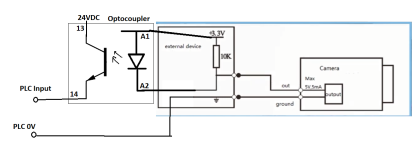
I have an IP camera, Amcrest IP8M-2493E, that has some digital I/O capability. It has 3 wires:
Alarm_IN1
Alarm_OUT1
Alarm_GND
I would like to integrate this I/O to a PLC. If I short the IN1 and GND, via relay contacts from my PLC, I get a signal to the camera and it does what I intend.
However, I can't figure out how to tie the camera output to a PLC input.
The camera Alarm interface is described in the manual as "1 channel In: 5mA 5VDC 1 channel Out: 300mA 12VDC". This seems to conflict with a sketch shown in a video (https://youtu.be/I7pGznSbsBs at the 1:51 mark) that shows +3.3V power and a 5V/5mA max. output capacity.
I've tried the 10k resistor in a pull up configuration with both 12VDC and 5VDC power. Should I be using a 3.3 volt power supply? With either 12VDC or 5VDC power, I get 12VDC or 5VDC between OUT1 and GND when the output is what I would call "OFF" and 0VDC when the output is what I would call "ON".
Great, the output voltage seems to be working. However when I attach either a 12VDC or 5VDC relay to the output, the relay does not change state and the voltage drops to some low amount.
Amcrest support is almost non-existent. What am I doing wrong? How do I interface this camera output to a signal level that I can do something with?
TIA.
Last edited:


