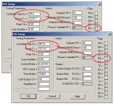
there's no such thing as a "simple" PID question ...
Greetings Mickey,
could you please point me to exactly where you found the quote you posted above? ...
Note: RG bit must be set to accept values exceeding 25.5 when using 5/03, 5/04, and 5/05 processors.
this information is incorrect ... now I know that it’s not your fault because you’re obviously quoting something from the official “book” with a copy-and-paste ... it’s just that I sort of have a hobby of finding obscure “quirks” like this in the official documentation and filing them away in my own little scrapbook ...
anyway ...
[attachment]
as shown above, it is entirely possible to enter a value greater than “25.5” even when the “RG” bit is turned OFF (that is, it is not “set”) ... the example I’ve pictured uses an SLC-5/05 processor ...
and now on to other things ...
Greetings Mathias,
I’m not sure that I understand exactly what you meant by your first post ... are you asking how to “calculate/determine/estimate” the appropriate values for “Kc” and for “Ti”? ... if so, then the rest of this post will be a waste of your time ... but I’m going to assume (gosh I hate that word) that what you ASKED is exactly what you MEANT ... in that case:
first ... since your SLC-5/05 processor supports it, just go ahead and turn the “RG” bit ON (=1) ... this (as shown in the picture above) will give you two decimal places of resolution for your “Kc” and your “Ti” entries ... with the “RG” bit turned OFF (=0) you will only have one decimal place of resolution for the “Kc” and the “Ti” entries ... more resolution is a good thing ... turn the “RG” bit ON and leave it ON ...
now for the “Kc” setting (the one you called “p”) ... suppose that you’ve already decided that the amount of Proportional gain that your application requires is “99.15” ... in that case you should go to the PID Setup Screen and click on the “Kc” entry field ... then type in “9915” ... the software will automatically interpret this as “99.15” and display the value “99.15” in the “Kc” entry field ... note: if you want to dig a little bit deeper, go look at the value in “word 3” (of words 0 through 22) of your PID control block ... there you will see the (integer) value “9915” ... just remember that the PID will use the correct desired value “99.15” when it performs its calculations ...
just to nail this down ... suppose that your PID is set up as in the lower window in the picture above ... knowing how I set up this example might help you understand the units that seem to be confusing you ... notice that the “Smax” setting has been entered as “100” ... notice that the “Smin” setting has been left at “0” ... these settings mean that I want my PID to consider both its “setpoint” and its “input” as numbers which range in value from “0 to 100” ... as in “percent” of full scale ... notice that I’ve entered the Setpoint as “40” (for 40%) ... next I went to the PV (process variable – the PID’s input) location on the data table ... there I manually entered the value “6389” ... I had arrived at that number this way: 16383 times 0.39 equals 6389 ... the value “16383” is the PID’s way of expressing a “full scale” input reading ... the number “6389” is thus a 39% input reading ... specifically, by manually entering the value “6389” into the PV location, I’ve told my PID that the input is 1% below the desired Setpoint ... this results in the PID seeing an Error (a departure from the desired target) of 1% ... you might notice that the “Scaled Error SE” field displays a “rounded-off” value of 2% ... don’t let the “rounding off” confuse you ... now ... given the 1% Error and the “Kc” entry of “99.15”, the PID calculates an output this way: 99.15 times 0.01 equals 0.9915 ... this is an output (for the Proportional component) of 99.15% ... and that value (rounded off to “99”) is what is being displayed in the “Control Output CV (%)” field ...
note that the “Ti” entry of “327.67” results in a VERY small amount of Integral action ... that’s why it doesn’t immediately affect the PID’s output ... the “Control Output CV (%)” field will, however, eventually increase to “100” percent if we wait long enough for the small amount of Integral action to accumulate ...
assuming that I have correctly interpreted your question, the information above should have nailed down the entry of the “Kc” (or as you said, the “p”) setting ... if you need more than this (or something entirely different) then please post again with more details on what’s giving you trouble ...
as for the “Ti” (or as you said, the “i” setting) ... the same “how-to-enter-the-value” approach applies ... note that the units of this setting are in “minutes per repeat” ...
this post and
this post should help you understand how the PID interprets those particular units for the Integral term ...
since you said that you’re not worried about the “Kd” (or as you said, the “d”) setting then I’ll skip any discussion of it for now ...
disclaimer: the values used in the examples shown above are NOT realistic ... they are intended for educational purposes only ... please do NOT assume that they might be anywhere near correct for your application ...
I hope this helps ... if it doesn’t, please include some more detail in your next post again and I’ll try again ...


