Bottle Line simulator(needs help)

AliAzi

Member
Join Date
Nov 2020
Location
Saudi Arabia
Posts
6
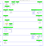
In the zip attached is the ladder program I made to control the bottle line simulator. Please I need help and to know, how can I keep

1.the run light flashing after
e.g 5 times detected broken glasses
, and

2.To start and stop the system without the use of the Run light as the controller, I wanted to be controlled by the start and stop buttons.


I don't mind any additional features for the simulator.
Thank you, guys.
 
I suggest you post it as a PDF (print it to pdf) and post it (it will give you more replies as not everybody has all types of PLC), I assume this is Rockwell also give us a clue to what the PLC is.
Also is this an assignment, if so post the documentation of the function as it is not clear.
For example "To start and stop the system without the use of the Run light as the controller, I wanted to be controlled by the start and stop buttons." does not make much sense.
"if a broken Glasses is detected 5 times stop the system" This is ambiguous as if you get one bottle on each production run then after five production runs the system will stop do you mean if 5 broken bottles are detected within a time frame or production run stop or does this mean 5 broken glasses in a row ? how and when do you reset the count back to zero ?.
 
Last edited:
Show your work

Caveat I


@parky raises several valid objections; the OP should address those first. I made several assumptions below that could well be inconsistent with the problem statement; also, I did not stop the process after the fifth broken glass event.


Answers to what I think are the OP's questions


To start and stop the system I suggest the Start/Stop design pattern cf. Contact & Coil's Patterns of Ladder Logic Programming web page (search for the terms in blue); that circuit is used in almost every ladder application, in a plethora of different forms.


Once you have done that, you need to separate the [run light] discrete output from the [running state] internal bit (the latter is controlled by the Start/Stop pattern above).


Then the task is to make the [run light] bit be

  • solid 1 when the broken glass event count is less than 5
  • flashing (1 then 0 then 1 ...) when that counter is 5 or more
There are many ways to flash a light (toggle a bit according to a repeating timer's state) that can be found on the 'net. E.g. there are several shown here (although the focus there was on the precision of the timing).


After the OP does their search and research, and programs a flashing circuit, where there are two states (bits): flash-on; flash-off, there are the cases they will have to control:

  1. Light is 1 when flash-on is 1; count does not matter
  2. Light is 0 when flash-off is 1 and count is 5 or more
Note that flash-off = [NOT flash-on]. So the desired behavior can be restated as

  1. Light is on when flash-on is 1
  2. Light is off when flash-on is 0 and count is 5 or more
Case 2 can be inverted using one of DeMorgan's Laws i.e.

  • NOT(A and B) = (NOT A) or (NOT B)
to state when the light is not off:

  1. Light is on when flash-on is 1 (no change)
  2. NOT (Light is off) when NOT (flash-on is 0) OR NOT (count is 5 or more)
Removing the NOTs in the second case:

  1. NOT (Light is not off) is the same as (Light is on)
  2. NOT (flash-on is 0) is the same as (flash-on is 1)
  3. NOT (count is 5 or more) is the same as (count < 5)
So the two conditions now become:

  1. (Light is on) when (flash-on is 1)
  2. (Light is on) when (flash-on is 1) OR (count < 5)
Note that, although we have played with the expression of the second case, individually they still represent the logic of the original lines i.e. case 1 is when flash-on is 1, and case 2 is only used when flash-on is 0, i.e. for case 2 (flash-on is 0) is True and (flash-on is 1) is False. So the second case can be further simplified:

  1. (Light is on) when (flash-on is 1)
  2. (Light is on) when (False) OR (count < 5)
and because [False OR A] is A:

  1. (Light is on) when (flash-on is 1)
  2. (Light is on) when (count < 5)
Those two cases represent mutually exclusive and distinct time periods, which periods together represent all time. So those two cases can be combined to represent the state of the light for all time. Doing that combination and conversion to ladder is left as an exercise for the OP.


Caveat II

I showed all the logic steps in painful detail here because the OP seems to be new to the game; after some experience I am sure they will be doing all of those steps in their head and coding directly from the problem statement.


And finally, here is a working example, with only the process model simulation shown.
 
Last edited:
I looked quickly at the file he sent only in word pad and it contains symbols for a filler of some sorts as well as glass broken logic, I did not look at the logic though.
I assume the process is:
Start/stop latch (also stopped by 5 broken glasses alarm)
Uses the alarm ored with a flash bit with the run latch to enable the lamp. I did it in 6 lines of code but assuming this is an assignment I will not divulge the code at least not until I see a PDF of what the OP has got as I could not open the file as a project.
 
I had six rungs too, which included a minimal simulator


I think the problem statement is here or here, and maybe this paper., or maybe starting at slide 52 here.


Anyway, I think I have the OP's rungs ported to .RSS, O:2 became O:0 and I:1 became I:0.


PDF is attached; I don't yet know what object to pass the RESet instruction on rung 0001 of LAD 3; probably the broken glass counter.
 
To the OP (@AliAzi):


There is a duplicate OTE in the main program (Output O:2.0/10 is assigned a value in both Rung 0000 and Rung 0013); almost everyone makes that mistake at some point, but it is a problem that must be fixed. Porgrams should assign a value (0 or 1) to an output in only ONE place when using OTEs; some PLC programming environments will not ownload such a program to a PLC.


To get to the OP questions, there will need to be a local "ON" bit (e.g. B3:0/n) that is assigned by the start/stop circuit in rung 0000, and then separate logic to control the light (O:2.0/10) to be off, on, or flashing.


Also, I know almost everyone uses ping-pong timers to implement flashing the first time, but all that is needed is a single self-repeating timer and then the flash can be based on the instantaneous state of the .ACCumulator for example, a 0.8s period, 50% duty cycle flasher could be implemented like this:


Code:
  do_flash  tmr.DN
----] [-------]/[---[TON       tmr]----
                    [Timebase  0.1]
                    [Preset      8]

  tmr.ACC/2         flasher_out
-----] [----------------( )-----
And there are even simpler methods than that.


TL;DR


The PDF is updated and attached. I added some comments; they are based on this page, but they are guesses at best. Still no changes to the (broken) functionality.


There are also duplicates of three rungs from LAD #2 in LAD #3, but LAD #3 is not called (unless perhaps via STI), so it does not matter.
 
I haven't had a chance to look through ANY of the attachments - but I'm GUESSING that he's working on the Bottle Line Simulator in the LogixPro software ...

if so, the link below might be of help ...

http://www.thelearningpit.com/lp/doc/bot/bottle.html

stay safe ... stay well ...


I thought that too but there are several descriptions (LSn) at the bottom of the .RSL file that seem to come from other similar exercises.
 
Here is a quick & dirty reject count plus how to use the run lamp as an alarm as well.
The latch bit is the run system bit, when a count of 5 broken glasses has been detected the run bit goes off but the lamp will flash, the whole process will re-start & reset the count on a start.
EDIT: Ignore the timer was going to create a flasher but used one of the time base bits instead.

REJECT.png
 
Sweet! But what is this R-A-like-fu from @parky ;)?


Also, it's qualified as "quick and dirty," so this is not meant as a critique, rather an alert to a feature/gotcha:


On fifth reject (fifth rising edge of [REJECT_BIT I:0/2]), system stops immediately because of [XIO ALARM B3:0/1], good. However note that fifth rejected bottle is probably still at detection point.


On a restart (input [START I0:0] becomes 1), when [REJECT_COUNT C5:0] is reset (rung 0006) and [RUN_LATCH B3:0/0] eventually becomes 1, [REJECT_BIT] may still be 1 as conveyor will not have moved much in two scans, so that fifth reject from the previous run is counted again as the first reject on the restart.


One solution would be to [XIO REJECT_BIT] to trigger CTU, instead of XIC, but that would change reject offset in any BSR/BSLs.


Anyway, just a thought and not meant as a critique.


P.S. using an S4:4 bit for flashing is a sweet hack.
 
Ha Ha. I was waiting for your reply, As I have not written anything for the reject it will depend on on it is coded and if the reject is initiated when the bottle is at detection point. it would be quite simple to delay the stop until a reject has completed the cycle, after all, we are supposed to be guiding this OP not exactly writing it. but yes some valid points.
 
Yes you are lol, but in a good way, this problem brings back memories of a job I was called to at a brewery to look at a filler, apparently, this was purchased from Italy but they could not get an engineer to commission it. I opened the panel & to my shock it was all relays, hundreds of them. The problem was very similar to this one, A broken bottle detected would spray high speed jet of water to clear the broken bottle, on a set number of continuous break detection (think it was 4) the machine would stop. This bit was not working, looking at the drawings I struggled to find out what the problem was so I decided to start from scratch, a quick sketch & a bunch of relays timers etc. from the local supplier I created my own and got it working. I don't think the original relay logic could have even worked at all looking at the logic, I certainly could not see how it would work.
By the way this filler was capable of nearly a 1000 bottles a minute, pretty fast for it's day.
 

Similar Topics

Can someone explain to me why thelearningpit use 3 bsl in parallel, and why the input are like this. And how if a bottle is defected in the start...
Replies
4
Views
2,040
Hi, I am new to PLC programming. Myself and several co-workers are taking a PLC class and we are using the logixPro to learn on, Our problem is...
Replies
20
Views
24,436
Hello, I am trying to solve the bottle line simulation, but I can't understand the basics, and why we are using BSL and BSR, so can anyone provide...
Replies
3
Views
2,964
[OSR] Using BSL instructions When working on rslogix.pro lab (bottle line simulation). Lab exercises 1,2,3,4 worked fine. However, when putting 3...
Replies
43
Views
19,969
Hi everyone! i got a problem in creating the flowchart for my Bottle Line simulation system. http://youtu.be/om5DGgxdmaU i used "Bit shift left"...
Replies
2
Views
3,861
Back
Top Bottom