Combining PLC outputs to a single output

Sprayman

Member
Join Date
Jan 2020
Location
Chicago
Posts
50
Hi there,

Quick Question. I have 2 PLCs and 2 solenoids. I would like to wire these up so that If either one turns on, it will turn on both Solenoids.

My initial thought is to bring both outputs to a single wire and then wire both solenoids to this.

My question is. Would doing this destroy a PLC? For example.

If PLC-2 Outputs 24V and turns on both solenoids. Would PLC-1 see this potential and ignore it? or would I generate some magic smoke?

These PLCs are internally made so I am not sure about the schematic exactly. Just wondering what the rule of thumb is for this kind of setup.

Thanks!

If both PLCs' outputs are fed from the same power supply you might be able to get away with tying them together, but I wouldn't recommend it.

I agree with drforsythe, the way to do it is to have each output fire a relay, then wire the solenoid through a NO contact on each relay in parallel.
 
just lockout logic is fine.

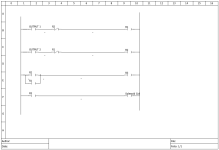
can be wired just like ladder would show

I'm not sure what the "rule of thumb" would be, but I always hated backfeeding anything, you never know what kind of wonky stuff can happen when things aren't contactor based and you have electronics holding back voltage from somewhere.

1_diagram.png
 
just lockout logic is fine.

can be wired just like ladder would show
...

Electrical just-enough-to-be-dangerous person here.

I am assuming that post is using ladder as a proxy for physical relays and wiring, so the [NC R1] and [NC R2] on rows B and C represent one pole of the output side of the relays, yes?

And the ORed [NO R1] and [NO R2] on row E represent a second pole of the output side of the relays, yes?

My uneducated understanding makes me ask what does the lockout buy here? R3 is going to back feed that second pole of whichever of R1 or R2 is not turned "on" first, but that second pole is isolated from either [OUTPUT 1] or [OUTPUT 2] anyway since those are relays.

I am not trying to be a troll; my assumption is that @IanM8040 is making a good suggestion and I have an opportunity to learn summat here. Thanks.


more or less, the Outputs 1 and 2 are the output voltage from the PLC, energizing the coils of R1 and R2 respectively. doing this means that either relay would turn on and not have a second output tied to the same coil.

then because my assumption was that there are two solenoids that need to turn on if either output commands it. then you have a direct 24v from the main feed through one of two NO contacts, only one can be on at a time.


with R3, I did forget to add the second solenoid off that relays NO contact power. The thing I think is being avoided here is having both coils being turned off and having voltage spikes flow back and damaging outputs. of course we can add surge suppressor diodes, but IMO it's always best to take best practices in isolation, especially if somethings fails closed instead of open.
 
Last edited:
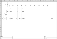
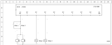
I've just been playing with a free software called Qelectrotech. Don't know my way around it very well at the moment, but this is more in line with the electrical schematic of it. I did plenty of electrical drawings in single line ladder logic previously, it all works the same as long as the symbols are accurate. Obviously just substitute the second output location from Output 2, to a separate card, sharing the same 24v system, and it would work fine.

2diagram.png
 
Still waiting for the light to come on, and I apologize for being so thick, but how does all of that, with its three relays, two of which are DPDT, protect one output turned off from being backfed, when the other output is turned on, any more than this with only two SPST relays?

Or is it only a spike on the 0VDC bus that is being protected against?

xxx.png
 
Still waiting for the light to come on, and I apologize for being so thick, but how does all of that, with its three relays, two of which are DPDT, protect one output turned off from being backfed, when the other output is turned on, any more than this with only two SPST relays?

Or is it only a spike on the 0VDC bus that is being protected against?

View attachment 60214

your 100% right and I just overcomplicated it 🍻

think I was just stuck on keeping them isolated and didn't realize I threw an extra step in there!
 
I think an interesting idea was mentioned in another version of this thread. That would be OUT1 of PLC1 applies voltage to IN1 of PLC2, and PLC2 then has a single output that powers either 2 small solenoids, or another small relay to power 2 decently sized solenoids.

lots of ways to make it happen, just depends on how complicated (or over complicated) it needs to be. I would still, in the end, try to avoid tying two outputs directly together.
 
... didn't realize I threw an extra step in there!


Thanks for the followup. In the end either way should work though, so no big deal.

Yeah, I too was wondering about routing out 2 to plc 1 or vice versa; could also be done with produce/consume as you infer if adequate comms exist. It may depend on whether the system is expected to work if one of the PLCs is out of commission.

better wash up for the exodontia DR.
 
So just to clarify, There is no ladder logic control on this. It is hardcoded.

I just looked at the schematic and there are no internal diodes so I would be sending 24V straight to ground through the output which I would think is a bad thing?

But ya I think backfeeding 24V into an output is a bad idea ...
 
I just looked at the schematic and there are no internal diodes so I would be sending 24V straight to ground through the output which I would think is a bad thing?


Not quite straight to ground, presumably the coil has some resistance; a coil resistance of anywhere from 50Ω to 2kΩ would limit current from 24V output to anywhere from 480mA to 12mA, no?

So it all depends on the current capacity of the outputs and the relays chosen, which we still do not know.
 

Similar Topics

Hi, I have a functions which extends codes generation for RFID tags. Basically it takes a char and splits it's hex value over 2 chars. I cannot...
Replies
24
Views
9,443
I'm onsite right now and I'm trying to decide how to proceed. I need to make some major edits to the Micrologix 1400 file, but the guy with the...
Replies
9
Views
1,157
Hello, I am trying to write a logic to control a pump. I have my logic as attached. Is there a way to do Auto and Manual control without having...
Replies
12
Views
2,719
Hi all. I’m currently trying to combine 3 memory words in to a single display on a weintek hmi as I want to display running time. I have the...
Replies
4
Views
1,827
I have an application where I need around 60 Amps of 24V. Most 24V PS go up to 40A, so I need to be able to add them in parallel. Puls power...
Replies
36
Views
10,365
Back
Top Bottom