OT........110VAC 3 Phase......??

The volage reading were posted...

yes, I see them now that I look closely - back in post #20 ...

so ... this thing was installed ONCE and burned up some components ...

then installed AGAIN - which is where it is located now - and running correctly ...

and will be installed AGAIN in the future - at the final customer's facility ...

is that right? ... if so, it looks like we're done here ...

one more thing: I still think that you need to get your hands on a decent manual ... I don't see how you're going to get away with handing this thing over to the final customer without having some documenation to go along with it ...
 
Alaric said:
For reference here is a picture of typical US 120/208 and 120/240 volt transformer secondaries.

a011608a.JPG


The first shows 120/208 three phase. The transformer has a WYE secondary and 120V is derived between any leg and the neutral. The line-line voltage is 208V.

The second shows 120/240 three phase. The transformer has a Delta secondary with a center tap in one of the windings. 120 V can only be dervied between the center tap and the ends of the center tapped winding (B-N and C-N in the lower drawing). Nothing should ever be connected between A and N. The voltage between A and N is 208V. This is mainly found in commercial three phase services.

Under the codes in NewZealand and I believe in all European based codes the transformer secondary winding are as your first drawing we call it the STAR point you call it WYE this is how the Neutral is achieved on 3 phase transformers, used in residential or industy, smaller rural transformers, use centre tapped 2 phases only to achieve the nuetral.

In our cases the voltages would be 400 / 230 volt in place of your 208 /120 volt,

The second drawing would not be allowable under our codes and I believe that to be the same in all European based codes.
I believe South America follows the European codes which is where this machine was made.

Thanks Alaric those transformer secondary winding drawings they have answered why the Americans achieve some of the voltages that I read descriptions of and I was thinking It could only be done as per the second drawing.
 
Last edited:
Gil47 said:
...
The second drawing would not be allowable under our codes and I believe that to be the same in all European based codes.
I believe South America follows the European codes which is where this machine was made.

Thanks Alaric those transformer secondary winding drawings they have answered why the Americans achieve some of the voltages that I read descriptions of and I was thinking It could only be done as per the second drawing.


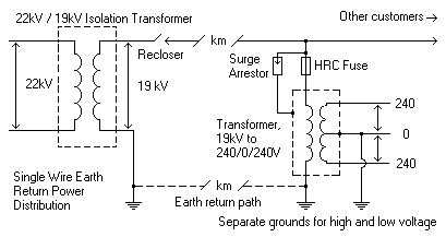
One of the reasons for the center tapped Delta in the US is to permit a less expensive way of delivierng 120V and 240V power to rural residences, which can be a considerable distance apart. For homes/farms that are really out in the sticks some utilities use a single wire earth return service - those must use a center tapped transformer to provide 120/240.
Swer.gif


Most home applicances operate at 110V, but stoves, clothes dryers, air conditoners, and electric heaters are operated at 240V, so there is a need to provide that voltage as well. Also, some of the woodworking equipment (expensive hobby) in my garage requires 240V.

Due to the large installed base of 240 heating appicances we are, for better or worse, stuck with it even where 208 three phase would be available and make more sense in urban and suburban locations.

Most electricity providers in the US are private for profit corporations, not government entities - and while they do have industry standards and work together, they are not compelled to do so. So there is some minor non-uniformity.

IMO, Europe got the voltage right but the frequency wrong, while the US got the frequency right but the voltage wrong.
 
Good job on photos.

OK so from post 20 you have 4 wire 208 / 120. Basically wye connected with neutral. Panel looks good they even phase taped the service conductors and HOT DAMN even got it right.

Your voltage readings in post 20 (?) confirm you have 208/120 nominal. Readings are a little higher than that but that is OK.

IN the panel the tripped breaker looks like it is feeding two black conductors. The three breakers are independent. Either tie them together with a tie bar or get a 3 pole breaker (best practice). CAREFUL when feed two loads with one leg of a three phase circuit like what I see. IF they are both fully loaded AND trip breaker (only the one) then you will single phase every motor.

Also you CAN direct wire SO cord into a panel. Done all the time.

You are right the person who put this togethr cobblied it pretty good.

For all I know you may be a master electrician but from the sounds of it you are not. IF you decide to fix yourself you are actually in pretty good shape.
Here is where to go.
1. I would use conduit from the panel to the receptacle. Pull in 5 conductors ie the 3 phases neutral and ground. In indoors use metal boxes and bond them to ground. If outdoors get good plastic boxes with good covers and ensure they are listed for at minimum raintite or washdown 4X.
2. YOu will probably need a 5 pin receptacle and plug. Mount receptacle so cap is pointing down by the way. It will drain better
3. Get 5 conductor SO cord. Use phase tape so that the conductor colors at each end of So are consistant with those in panel ie A phase black B red C blue white neut and green ground.
4. Chacke with factory to ensure 230 volt motors can run on 208.
5. Double check all motors connected for 230. with your voltage at 215 phasse to phase (was it? you should be OK.
6. Double check with factory to ensure rest of components will be OK on 208.

Gotta go to work and fix that SNAFU wiring.

Dan Bentler


XtremeIN said:
DSC04220.JPG

OZONE Machine

DSC04222.JPG

Motor/Pump plate

DSC04225.JPG

Control Panel

DSC04226.JPG

Wires 01, 02, and 03 are the three 110 feed lines and 04 goes to a panel neutral

DSC04227.JPG

Control Panel Circuit Breaker, the three wires on top are 01, 02, and 03 from previous picture

DSC04230.JPG

Panel feeding the 110

DSC04231.JPG

close up of panel

DSC04232.JPG

junction box

DSC04233.JPG

Machine outlet, white wire goes to a 250 Single Phase outlet Panel Neutral

I will get some reading and be back.......
Thanks,
Micheal
 
Your voltage readings in post 20 (?) confirm you have 208/120 nominal. Readings are a little higher than that but that is OK.

Dan,

I think their building transformer (480 to 208/120) is probably set on the second transformer tap for 2.5% Below Normal voltage. Usually there are 6 taps, two above normal voltage, and four taps for below normal. Each tap raises or lowers the secondary voltage by 2.5%.

If you have some 240 volt motors but your transformer is a 208 volt 3-phase unit, a common solution is to jump down 1 or 2 transformer taps. First one gets your 208 + .025(208) = 213.2. Next one gives you 208 + .050(208) = 218.4 volts. Most 240 volt motors will run on 218 volts, while the 120 volt receptacle circuits jump to 126 volts. Even the 208 volt equipment will be perfectly happy with a 5% higher voltage.

I have done it many times and it is a cheap, workable solution.
 

Similar Topics

Hi everyone and happy new year y’all. Have anyone use a 110 Vac instrumentation cable for a 220 Vac device?
Replies
7
Views
2,185
I have some 24VDC contact signals and 115VAC to the coil of a contactor to go to an enclosure. Is there anything wrong with running the 115VAC...
Replies
5
Views
2,129
Hello anyone, i need your helping. coz im building switchboard send to USA with UL label. i could find all component with UL listed but...
Replies
1
Views
3,708
I am looking for a solution for how to read the presence of a 110 vac signal when the plc I am using only has dc source or sink inputs. I know...
Replies
7
Views
2,564
What would happen if you ran a 60Hz Single Phase Motor on 50Hz supply?
Replies
6
Views
522
Back
Top Bottom