Eplan P8, wires?

Join Date
Jun 2007
Location
Oxford, UK
Posts
163
Hello everybody,

once again i am stuck and seem like an idiot asking a simple question.
We have recently upgraded to Eplan P8 and i have just started to use it. i am not very experienced in using Eplan but my colleagues are and they are stumped as well.

i want to draw a connection between 2 points. i just moved a symbol of a PD trigger switch along slightly and i want to connect it up as it was before but the connection wires have been deleted when i moved it. can i reconnect these? how do i make the connections? i thought they were automatic.

I havent got a clue...HELP!!!
 
To start with: I do not have P8 but a lower version.

Normally they are autoconnecting. If this does not happen you can remove the symbols or use the 'corners' (sorry, i don't know the english name for it but there are 4 of them let's say L-shaped).

In the past i have noticed that with some symbols this is also not possible because the 'connecting-point' of the symbol, after moving the symbol, lies between two grid-points. It's the insert-point of the symbol what stays on the grid. The insertpoints can be made vissible with the key 'I'.
 
What I always do, is to delete the symbol and re-insert it at 'the correct position'. The auto-connectionfunction will work again. Don't bother about the insert-point it is not important at that moment, only if you remove it.
 
Im not sure whether it is possible to turn on and off the auto connect. but i am pretty sure that mine is not working. do you know of a reason for this?
 
I haven't used P8 still on EPLAN 5.7.

Just wondered if this was the same for all the symbols or just this one? If it is just this symbol, is it a symbol you've created and forgot to add the connection points?
 
i am so new to this that i barely know whats going on.

basically what ive got is a drawing to represent come trigger PDs and Photocells using Symbols. im editing not creating so i just wanted to move the lines that represent the wires from the left hand side to the right hand side. sounds simple....but i have a feeling that our auto connect doesnt work as when i line up a right angled connector it will not connect to the points i aline it too.

the connection point for this symbol seems to be in the middle.

does this make any sense?
 
Connecting points represent the various connections on the device so normally you'd have more than one. It certainly sounds like what your doing should work.
Just a thought, was the drawing you're editing originally done in Eplan or was it imported from say AutoCad (something we sometimes do) if this is the case you lose the intelligence and the lines won't autoconnect. A test could be to just add a couple of angles in line with one another and see if they join?
 
hmmm...no it wasnt imported from autocad but i have copied this drawing to a temp folder so i can edit it.
But this Drawing was drawn on an older version. Version 5 i think. it has been within the last few weeks that we started using P8. Would it be worth me looking at redrawing the page or using a different symbol?

i did your test and they do not join together but if i use a function called "align to grid" and then select the 2 angles they will align and join to one another. this however is really annoying as they will always align to the grid which means that the drawing is hard to fit on a page.

Im have a feeling that when i started using the P8 it did autoconnect. i am slightly confused why it is not autoconnecting.
 
bmw_apprentice said:
i did your test and they do not join together but if i use a function called "align to grid" and then select the 2 angles they will align and join to one another. this however is really annoying as they will always align to the grid which means that the drawing is hard to fit on a page.

They do have to be perfectly aligned to autoconnect. If the grid spacing is too high, there should be a setting somewhere to make it smaller? I think in Eplan this was done by changing the increment setting.
 
Last edited:
Daer BMW apprentice,
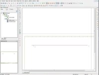
Yes I was having the same problem. If you will add two angles (right down) they will not autoconnect. Try one right and one left and they will autoconnect as i am sending screenshot for assistance
Thanks

EPLAN.jpg
 
for autoconnection you should always see that the connection point of the devices should be always aligned to grid in EPLAN P8 i.e. when you are taking the templates at the begining of the drawing at that time by default grid is taken.........

this grid you can change by going to the properties of the page, to make autoconnection follow the procedure it will help u i m sure

1. Insert the device you want to connect.

2. with the dimension tool measure the distance between 2 connection points.

3. It will depend upon the template chosen by you.

4. Suppose it is 8mm.

5. than make ur grid 4mm from the properties.

6. After that insert the symbol again.

7. Align to grid the symbol by the same function.

8. After that bring any of the other symbols or terminals or any type of bending & make use of align to grid for that also it will auto connect.

pls let me kno if it is working or not

for me it is working fine.
 

Similar Topics

On all pages of my project i have a lot of information, texts and details that should not not be shown. I can remove them for each part apart from...
Replies
0
Views
31
Good morning colleagues, Does anyone know the cost of an EPLAN license and where I can buy it from an official distributor?
Replies
1
Views
190
Hi, I searched in forum but haven't found anything similar.. I am looking for Eplan .edz files/macros. I don't have access to data portal so maybe...
Replies
2
Views
1,935
Hello everyone. Currently I am using Eplan p8 and faced (while creating a panel) with a challenge in finding a device called DIN mounting rail...
Replies
10
Views
3,414
Hi All I am new to Eplan and I inherited a project that was designed in Eplan and needs rework. I was informed that the Eplan project was on the...
Replies
8
Views
4,184
Back
Top Bottom