RPI and RTS and Filter settings for ControlLogix modules ...

Ron Beaufort

Lifetime Supporting Member
Join Date
Jul 2002
Location
Charleston, SC
Posts
5,701
Greetings to all ...

I had an exceptionally bright and highly motivated student in one of my ControlLogix PID classes the other day ... this guy was absolutely determined to "boldly go" where others had never been ...

some of the things that he was particularly interested in were the following settings for the 1756-IF8 analog input modules that we normally use for the Hotrod loop tuning experiments ...

(a) the RPI (Requested Packet Interval) setting ...
(b) the RTS (Real Time Sample Period) setting ...
(c) the Module Filter setting ... and ...
(d) the Digital Filter setting ...

all of these were important to him since he was personally involved in an on-going project back at his plant – and getting as fast a response as possible from the PID was considered a major objective of the project ...

anyway ...

I was able to pull together a few demonstrations in the lab which helped us work through our most pressing concerns ... since then, I've cleaned up SOME (but definitely not ALL) of the rough edges ... at some point in the future I might nail all of these down into some sort of "lesson" – but for now I thought that my preliminary notes might possibly be of interest to the forum ... note: this is probably overkill for most people – since I don't recall that the topic has ever come up for discussion before ... but I offer it for what it's worth ...

the basic idea for the experiments was to connect TWO 1756-IF8 analog input modules in parallel with each other – so that each module would sample exactly the same voltage input signal ... the analog output signal was provided by a 1756-OF4 analog output module ... I kludged together (no other term for it) a method of injecting a certain amount of artificial "noise" into the output signal by chattering a separate relay output (details available upon request) ...

so ...

by trending the various signals I've been able to come up with a series of graphs which answer all of my personal requirements about this topic ... if you're interested in this project, I suggest the following game plan:

(1) print out the RPI_RTS_Spreadsheet.PDF file which shows the setups for the various tests that I ran ...

(2) right-click the 01.PNG picture file and select "Preview" from the Windows pop-up menu ... then use the right and left arrow keys on your keyboard to do a simple "slide show" and cycle through the figures ...

you might also want to open the RPI_RTS_Figures.DOC file which shows the various graphs all in a series ... I recommend that you view this file at 150% zoom size for best results ...

if anyone has any questions, I'll be happy to try to answer them – but right now I'm tied up in other some rather pressing projects – so it might be awhile before I'll have time to nail things down ...

party on ...
 
Last edited:
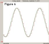
sample graph ...

just a quick preview - chosen at random ... this is a two second graph ...

the green trace shows a "faster" RTS setting of 11 ms ...
the red trace shows a "slower" (default) setting for RTS of 100 ms ...

both traces are using an exceptionally "slow" setting of 750 ms for the RPI - which surprises many (most?) people by having just about ZERO adverse effects on this type of input signal ...

note: I've reversed the colors here to make the details easier to see in the JPG format required by the forum ...

06_white.JPG
 
Last edited:
the trend was set to sample each millisecond ...

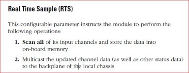
the biggest single issue if you just do a "quick read" of the setups – is that the RPI determines how often the module's data gets "updated" (sent/transmitted) over the local backplane to the processor ...

BUT ...

the data only gets "refreshed" (measured) from the FIELD CONNECTIONS at the RTS rate ...

analogy: suppose you set your RPI to order a daily newspaper – but you leave your RTS set for a weekly update ... you'll get a nice fresh newspaper on Sunday ... and you'll get another paper on Monday – but this one will be just a COPY of the same paper that you got on Sunday ... then you'll get another paper on Tuesday – but it will also be just another COPY of the same paper that you got on Sunday ... then you'll get another paper on Wednesday – but it will be yet another COPY of the same paper that you got on Sunday ... and so on ... you won't actually get a NEW (freshly written) newspaper until Sunday rolls around again ...

it seems that most people aren't expecting that – and so they set the RPI faster – while neglecting to speed up the ultra-important RTS setting ...

you can see that effect demonstrated in Figure 4 ...

note that all of this is based on ControlLogix analog input modules located in the "LOCAL" (processor-resident) chassis ... different rules apply in other situations ...
 
Last edited:
the trend was set to sample each millisecond ...
OK, this makes sense.
the biggest single issue if you just do a "quick read" of the setups – is that the RPI determines how often the module's data gets sent over the local backplane to the processor ...
This does too but obviously the module's data is getting back to the local CPU unless the CPU is being bypassed when getting the trend data.
 
obviously the module's data is getting back to the local CPU unless the CPU is being bypassed when getting the trend data.

in the sample shown (and in the other figures) there are TWO traces ... both are sampled from the same CPU for graphing purposes ...

in most experiments, ONE of the traces is provided by ONE input module with ONE particular configuration ... the OTHER trace is provided by ANOTHER input module with a DIFFERENT configuration ...

that arrangement lets me demonstrate how changing the various settings will affect the two data streams side-by-side on the same graph ...

note that the two modules are connected in parallel to the ONE voltage signal being examined ... specifically, BOTH modules are seeing EXACTLY the same signal ... any differences in the traces on the graphs are due to the configuration settings of the modules ...
 
Last edited:
Originally posted by Operaghost:

RPI only actually matters for remote modules.

...unless you AREN'T using realtime sampling. But thanks for the post. I didn't realise that the data got transferred at the RTS rate. In the past (if I used realtime sampling) I always made sure the module RPI was set faster than the RTS. I obviously didn't need to worry about that.

Keith
 
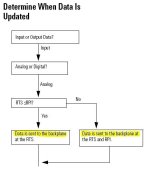
and here's another figure that might help further the discussion ... this is an excerpt from Page 63 of publication 1756-UM001G-EN-P dated January 2007 ...

technically there's nothing wrong with this part of the chart – but – most people don't realize that when the data is "sent to the backplane" it's often OLD DATA that's being sent ...

specifically, the term "Updated" used in the chart's title leads people to assume that the data will be "freshly measured" before being sent to the backplane ... that erroneous assumption can cause complications ...

flow_chart.JPG
 
Last edited:
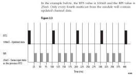
and the figure below is an excerpt from Page 2-6 of publication 1756-UM009B-EN-P dated June 2003 ... for my money, this one gives a much better idea of what's really going on with the measuring and the transfer of the data ...

piano.JPG
 
Last edited:
It was always my understanding that the RPI and RTS values should be the same - on the basis:-

1. No point having RTS faster than RPI, since you'd be sampling and converting the analog signal more often that it was sent to the controller.

2. No point having RPI faster than RTS, since you'd be sending the same data to the controller several times.

However, on re-reading the manual for the IF8 (and I assume all analog input modules perform the same), the following is the case.

A. Analog Input module in same chassis as owner-controller.

The module performs input conversion at the rate specified in the RTS value

THEN - updates the mulitcast message to the local chassis backplane

AND - resets the RPI timer.

Local modules therefore update the tags in the controller at the RTS rate...

IF - RTS is less than RPI, then RPI is virtually redundant,as it gets reset by the faster RTS.

IF - RPI is greater than RTS, then the data is multicast to the controller more frequently than the module converts the analog inputs - this to me is a waste of a network resource.


B. Analog Input module in different chassis to owner-controller.

The module performs input conversion at the rate specified in the RTS value

THEN - updates the mulitcast message to the local chassis backplane

AND - resets the RPI timer.

The RPI value then determines how frequently the data is transferred over the network to the owner-controller's chassis.

Notice that the RPI gets reset by an RTS, so how does the RPI ever "time-out" to trigger the transfer of data over the network? Answer - it doesn't - the RPI value is simply used as a parameter for the "streamimg" of data over the network.

The manual then goes into detail about "best case" and "worse case" scenarios for data-transfer, but concludes that you should set RPI equal to or less-than the RTS for most effficient operation.

Goto Top of Post
 
from daba:

It was always my understanding that the RPI and RTS values should be the same ...

as you pointed out in the rest of your post, you've changed your mind about that lately ... here is something else that I ran across while researching for this thread ...

Knowledgebase 32321

Can RPI and RTS be set to the same value?

It is not recommended. Increase the RPI to something greater than the RTS

Summary: Having the module configured with the RPI=RTS will allow the RPI timer to occasionally time-out, triggering an avalanche of other interrupt-generated activity on the module. Normally, when the RPI is set to a value greater than the RTS, the RPI timer is reset with each RTS transfer.

"triggering an avalanche" sounds like pretty bad stuff to me ... I haven't been able to duplicate anything that spectacular in the lab (but then I haven't tried really hard either) ...

party on ...
 
Last edited:
Thanks Ron,

In conclusion then:-

For a Local module : Use RTS to control update time (set RPI higher).

For a Remote module : Use RPI to control update time (set RTS lower).
 
What I should have said was...

.......

For a Remote module : Use RPI to control update time (set RTS higher).
 
comparing LOCAL and REMOTE analog setups ...

here are a few more screen shots for those who can't get enough of this stuff ...

basic ideas for this latest series of experiments:

I took the 1756-IF8 analog input module that had been giving the green trace out of the local chassis – and moved it into a remote chassis connected through a ControlNet bridge network ... I configured the module to "Use a scheduled connection over ControlNet" ...

the 1756-IF8 analog input module that was giving the red trace was left in the local chassis to allow side-by-side comparisons of a "Local" setup and a "Remote" setup during each of the experiments ...

keep in mind that the two modules were connected in parallel to the same voltage source – so both modules were seeing exactly the same input signal at all times ...

in each of the following experiments, the setting for the Module Filter was left at 1000 Hz ... the setting for the Digital Filter was left at 0 ms ...

the trend graph was set to sample the processor's data once each millisecond ...

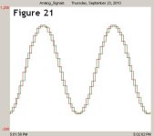
in Figure 21 both modules were configured as follows:

RPI = 11 ms
RTS = 100 ms

the red trace is from a LOCAL module ...
the green trace is from a REMOTE module ...

21.JPG
 
Last edited:

Similar Topics

In ControlLogix 5000, the AI module resets the RPI timer each time an RTS transfer occurs. What is the purpose for RPI timer be reset by RTS? If...
Replies
3
Views
4,181
Hi there I am new with this thing and i don't know how to connect Allen Bradley Micrologix 1200 PLC to Raspberry Pi using USB to RS485 in NodeRED...
Replies
3
Views
2,263
Hello all, I am using a temposonic R series linear transducer for positioning of a lower ram on a hydraulic powdered metal press. The transducer...
Replies
7
Views
1,932
Hello Ladies and Gents, I have some PLC to PLC communications using Produce and Consume. The data is not time sensitive, and I really only need...
Replies
16
Views
4,637
I am not very experienced in Rockwell PLCs and have run into a small problem, so I could do with a little bit of help. We have a redundant...
Replies
3
Views
2,488
Back
Top Bottom