Omron Zen Software

choover567

Member
Join Date
Feb 2012
Location
United States
Posts
5
Hi I am trying to use this software to build a profile for my solar chamber. It turns a series or certain of lights on and off at certain times of the day. I cant seem to figure out the timer in order to turn a light on and off for separate periods of time. I figured out how to do the flashing pulse and twin timer; but that's not exactly what I'm looking for. I think it may be a little bit more complex.

For example: Once the program starts, I'd like to wait 60 minutes, turn a light on for 60 Minutes, turn it off/wait for 2 hours, then turn the light back on for 8 Hours. If I could get an example of how this works I should be able to figure out the rest; but I am pretty new to this type of software. I attached what I have so far for a single light, using a basic timer. Any help would be greatly appreciated! Thanks!

Chris

Solar.JPG
 
Choo,

On your Rung 1, use I0 for a Start Pushbutton (instead of Q0). Q's are Outputs and using Q0 as you did creates a paradox that will not work.

Your program should look similar to this. This is one way to do it, maybe not the best or most efficient. I shortened the times to make it easier for you to see it work in the ZEN Simulator (changing Minutes to Seconds and Hours to Minutes). For your final version, you can adjust the times to your real values.

Also, to run this in the ZEN Simulator, you must change Input Switch I0 from N.O. to a Momentary Closed Contact (as a Stop Pushbutton would normally be for safety). You may use either the Input Pushbuttons or the ZEN Panel Buttons to Start or Stop this program. To run, click "ZEN, Start Simulator", then "ZEN, Change Operating Mode: RUN".
 
Last edited:
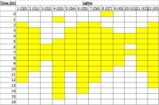
Thanks this circuit will actually work great! However, my concern is running out of timers. I can only add timers 1-9 and a-f and so if I used this circuit for each light ill eventually need more. I attached an example of the profile with all 12 lights. What you built before was for light number 4. So I guess my question is, is it possible to allow more timers to be used? Thanks!

Chris

Solar Light Profile.jpg
 
Please note that X0 thru X3 are expansion inputs. Y0 thru Y3 are expansion outputs.
 
Last edited:
In response to post #3. To get more timers, you could make one self resetting timer rung set up for 60 minutes. Let that timer increment a counter. I am speculating but it appears to be difficult to fit everything within the program capacity (memory/steps). Some of the experts here on the forum might be able to, but I don't have enough experience with this software.
 
Would you mind posting a new profile showing all 24 hours and corrected expansion output addresses? You might be able to use some twin timers, depending on the profile mapping.
 
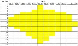
This is basically the same profile, simplified. I should be able to build this profile, however it wont be exactly what I'm looking for when it comes to actual testing. I had the lights scattered to imitate an actual day of sunlight in the middle east. The way the lights were placed effect sunrise and sunset. The other hours after hour 16 are just dark (night time). Anyway, I will build this profile I've attached, and once I have it up and running, using the start/pb circuit you gave me, I will fine tune it from there. You may be hearing from me in a week or so. Thanks for all your help! Any suggestions please, let me know!

Chris

Solar Profile 2.jpg
 
Attached is my attempt to follow your profile in post #8. The timers T0 thru T8 are the Start Timers. Timer Tf is for a 24 hr timebase, currently set up for 240 seconds (3min:59 seconds) to test. T0 thru T8 is for a 1 hr timebase, currently set at 10 seconds to test. P0 thru P6 is the stop time currently based on 10 seconds between steps and comparing time accumulated in Tf. To take out the " Daily Reset " feature, remove the normally closed contact M1 in rung 4 at position 2 (column 3). That would allow it to stop after one cycle. To manually restart, just push the Stop, then, push the Start again for another cycle.
 
Last edited:
Use one timer and then use the P Comparators for T0 >= to 0, T0 >= 1 etc
See the attached.
I have set the timer for 24 seconds instead of hours so you can see it work in the simulator.
I have only shown the first three outputs to show you the idea.
 
On your Rung 1, use I0 for a Start Pushbutton (instead of Q0). Q's are Outputs and using Q0 as you did creates a paradox that will not work.
Thanks this circuit will actually work great!

Chris,
Surely I must have missed something. I cannot see any way where your 2 rungs with Q0 as input and output would work at all. Will someone please explain this to me? I really want to know, because if "this circuit will actually work great", then everything I thought I knew has been thrown out the window, and I must start a rapid retraining program right away!

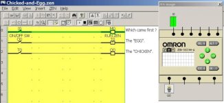
I recreated your ZEN rungs and tested. No matter how I set the timer or the timer contact, Q0 never goes on. See for your self in this picture. I added the first rung to show that the ZEN was in RUN mode.

I guess the age-old question of whether the chicken or the egg came first is still unanswered....

Chicken-and-Egg.jpg
 
Use one timer and then use the P Comparators for T0 >= to 0, T0 >= 1 etc
I agree with Moggie. You will have enough P contacts to handle your 24 time start and stop points. (See attached files).
 
@ Lancie,
I think when Chris said "Thanks this circuit will actually work great! " he was referring to your solution in post #2, not his proposed solution in post #1. By the way I like your solution in post #12 much better than mine in post #9. Your code is much easier to understand and change the settings.
 
Last edited:
:confused:

:oops:
By the way I like your solution in post #12 much better than mine in post #9.
Thanks. It is unfortunate that the complete problem was not stated in the first post, instead of the 8th. Is it low confidence and low self-esteem that prevents stating the entire problem right at the beginning, or what? Maybe they just want to talk to someone?

I suppose that for the beginners who can and do describe the problem concisely and completely, then the answer becomes self-obvious and the question never arrives here!
 
Last edited:
I suppose that for the beginners who can and do describe the problem concisely and completely, then the answer becomes self-obvious and the question never arrives here!

Agreed - and this question looks suspiciously like a homework assignment - very conveniently had 16 switching times to match the 16 P contacts available in the ZEN.
 

Similar Topics

I am very new so I will try to give as much information as possible. I cannot get a Prolific PL-2303TA USB to RS232 to connect to an Omron ZEN...
Replies
1
Views
1,588
Hi, after 30 years involved with automation I'm actually writing my first PLC program and am struggling a fair bit. My background is mechanical...
Replies
8
Views
1,875
Hi I am setting a system up as per the attached picture, 5 inputs that are always present. These are sensors I have in an injection mould, if...
Replies
5
Views
1,857
Hello all, new on here, and relatively new to plc programming. I am trying to write a program which counts as it receives a cycle end input, and...
Replies
4
Views
1,895
I am trying to write a program for a omron zen plc. 1st light on for 30 sec 2nd light on for 12 sec 3rd light on for 3 sec then start all over...
Replies
1
Views
1,332
Back
Top Bottom