Panelview Plus Multistate indicator

ErikG

Member
Join Date
Apr 2014
Location
Washington State
Posts
23
Using Factorytalk view ME and RSLOGIX5000 I am trying to use a multistate indicator on my Panelview plus that will become visible and display a variety of messages when certain conditions exist. (ie: e-stops, limit switches, motor overloads) I am using STRING data type within logix5000. How do I store all of my messages within logix5000, and then have them displayed 1 at a time in my multistate indicator?
 
You should store the messages in Multi-state indicator in PV, with each message have its own value in the tag. Then you can switch the values based on time from the PLC
 
If I have several tags that are active at one time, how do I get the PLC to only send 1 at a time? Right now If I have multiple conditions present, my multistate indicator flashes between messages. I want my first message to show up, then once that condition is no longer true, the next message comes up, and so on
 
The multistate indicator uses a numeric pointer tag, and the string messages are setup in the object. Ie,
value 0 = message 0
value 1 = message 1
value 99 = message 99

Almost sounds like you want the multistate indicator to cycle through the active messages, which it will do if you code in the PLC
 
There are several way to accomplish that task.
1. Would be to set your message in the alarm file.
Note that you can use more than one alarm list or display and Filter each one for values displayed.
2. The Multi-State is the way metioned. store message for each state and assign a tag to indicator and populate tag via the PLC.
3. Information Message Display list message and assign trigger values.
this method would use the INFO screen that's created when project is created.
4. String Display which might be more of what you want since your post metions strings in PLC. You could do this by using the insert variable option on the String Display. Where the variable could be the tag used by the PLC that list your string Text.
5. Local Messages same as info. Create messages and use trigger values. This is an object you can insert and size according to charactors needed for messages.

As Far as display one message at a time then use a DINT and Use The individual bits for Alarms. That way you can require DINT to equal Zero before alarm bit sets. Then it will be first come first serve and first must reset before allowing next alarm to set. Just be aware this is for info only. If you need multiple alarm actions then you should have alarm bit to protect system and use DINT for display.
 
Last edited:
We use a DINT store individual alarm states (though the idea could be expanded for more than 32 alarms). A routine within the PLC first tests the entire DINT if it is equal to zero. If so then a zero is placed into the message trigger value. The zero triggers a 'No Faults' message.

If the DINT is not equal to zero an index begins at zero and works its way to 31. If a bit is TRUE then the scan stops. The index + 1 is sent to the message trigger value and a timer is started, we found about 2 seconds is enough for a person to read the short alarm message. When the timer is done it is reset and the scan continues on to the other bits. So each of possibly multiple alarms gets its own turn. (Note: be sure to specifically reset the timer when done (RES) otherwise simultaneous alarms in adjacent bits do not restart the timer.)

Some messages require a different type of attention so we trigger different colors of the text and the enclosing frame to emphasize them.

As the alarms are cleared the messages stop showing up.
 
I have used Bernies method, and for picking messages from a bit file of up to hundreds of alarm bits, you may find the FBC instruction useful to generate the bit position of the first true alarm. What you describe, to keep the first alarm visible until that condition is cleared, just means you always start the compare at zero and stop at the first found, display it for a minimum viewing time. You can make the zero state of the multistate indicator completely invisible if you want, and use the PLC string files, by pointers as already described, but having the text in the PLC will mean reading all those strings over the communication link for all of them in the list, all the time that page is active.

Also, you are going to have to properly prioritize your alarms, which it appears is your intent, not to show every alarm that also happens to be true while "control power off" needs to be dealt with first, for example.
 
Bernie or Okie is there a way one of you could show me a sample of how to write this in my logic? I understand what your saying, but I'm having trouble figuring out how to write it.
 
Last edited:
Do you already have alarm logic that you need to tie to the multi state object?
In any case, you can choose the properties of the indicator value tag and add states, set the values for each state and determine how to interpret the value tag (LSB, value).

In the PLC, if there is already alarm logic setting up the value, you need to check for a change of that value, and when one occurs, set the PV display indicator tag to that number, and keep it that way for 2 seconds. When the timer is done, if no alarms exist, set the value back to zero, otherwise set it to the first alarm value found again.

If you are writing the alarm logic from scratch you can design it a number of ways to match what you want to display.
 
HI ErikG. Welcome to the forum. I have used the message display with great results. Like Bernie and OkiePC. What I do is let the first message display until it is fix or the operator can press a button on the screen to scroll down thru the messages.
 
No I dont have any alarm logic yet...I have just been playing around with it and I havnt figured out yet if I have multiple bits active at once representing different alarms how to get it to just take the first one and change my multistate...and then when that first one is cleared then go onto the next...right now if I have several bits active it just starts flashing between messages
 
I would advise analyzing all the alarms all the time, but limit how they reset your message display timer. Even though you only want the highest priority message to appear, you don't want it to appear for 7ms, or 150ms, or even 500ms, you want it to appear for 2 seconds for, as Bernie said, easy and efficient human reading, but also so that any alarm system on the other end of the wire, with its asynchronous processing, has time to log it if necessary.

Many alarm rungs are common in design, often having an expected command match up with expected position within a tolerance or within a time limit. Suppose your message display is set up to follow MSG_Int, you write your alarm logic to turn on and off bits in a file of your choice, for internal use by the process. You may need many of those alarm bits in the fault recovery or "return to auto" aspects of your control software, always process all of them, usually into bits so adding them into any other logic is simpler than a compare. Also, individual alarm states may have their own arrangements as members of Dints or Ints depending on how many there are.

For the MSG value, have a timer that runs continuously, MSG_Dwell, we'll call it on an unconditional rung...how about we put it on the fist rung of he alarm logic, and put all the alarm logic in one file that runs as one of the last, if not the very last routine in the code.

For each and every alarm rung, add a branch that, only when MSG_Dwell is done, (XIC MSG_Dwell.DN), MOV the alarm code for this particular message into the display value and RES MSG_Dwell. On the next alarm rung processed, MSG_Dwell will not be done, so even if the internal logic is true for the condition, and you can use that in your control, the MSG value is not updated until the timer (1.8 to 3 seconds depending on message length) is done.

Also, I write my alarm logic so that alarms whose conditions remain true cannot be reset to prevent adding repeat alarms to any lists or logs. I do this by putting the reset logic for each alarm as a branch around the alarm conditions with XIC of the alarm bit itself and the NOT reset command. If the conditions are still true, the alarm is still true no matter how fast, how many times or how long in duration you press reset.

Have you ever programmed logic to measure the speed at which operators can press reset? If not I highly recommend the exercise, it is entertaining for sure.
 
Last edited:
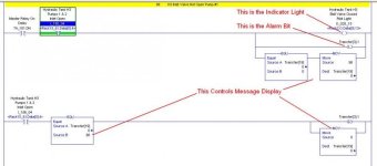
Here is an option for your display. If you only want one at a time until cleared. It Requires word to = 0 before trigger of message. The Logic Below Looks for the position of a Valve. If Valve is not open then it activates the indicator light it sets the alarm bit And Then If the Alarm Word = 0 then It Moves the Message Number Into the Alarm Word. So Now my Alarm Word is not = 0 and no other Alarm messages will appear. Then the second Rung is the Reset. If Valve is open and The Alarm Word is Equal to Message Number then Reset Alarm Bit and Move 0 Into Alarm Word. So Now we allow next message Because we have Reset Alarm Word To Zero And We Can Use The Alarm Word to display messages.

Alarm.jpg
 
PanelView Info Message

Hello. I know this is a slightly older post, but I came across this and got some good information. I have a few more questions though. I am in the final stages of my first large ladder logic and panelview project and I am having some difficulties in understanding how to set up information messages.
I understand the alarm setup and I can have those display when I get certain alarms in my logic going on. But there are items on this project that I would like to display when a bit in my logic goes on an information message pops up. The operator must then acknowledge this to remove the message from the screen. It looks like to me I can only reference one tag though in the information setup editor. So if I have different tags in my logic that are turned on how would I set up the editor to display info messages.
Example: When safety chuck is open. ChuckAlarm bit turns on.
When the safety light curtain is crossed. Safety_Curtain_Inhibit bit turns on.
How can I have these either displayed at the same time or one after another until the operator acknowledges them and the chuck is closed or the safety light curtain is no longer blocked.
I am sorry if this is a little convoluted I have been spinning my wheels and just need a point in the right direction. If more explanation is needed or code is required please ask.
 
To use the information display you will have to create a DINT decicated for infomation display numbers. Then do the same thing as post above. Assign a numeric value for each action and parallel the MOVe with your Bit.
 

Similar Topics

Hi, This is my first post and my first time programming a panelview plus 1250. Im looking for some help with something I am trying to do with...
Replies
2
Views
1,336
How do you determine what a multistate indicator is going to do when it is pressed? I have an existing application with a gotoDisplayButton...
Replies
10
Views
12,445
I need a multistate indicator with a trigger type LSB that will span four integers. So, I created it with the connection tag "MESSAGE" assigned...
Replies
2
Views
4,068
The application looks fine in the test run at the development node(my computer), but when transfer to the Panel View I can see some of the labels...
Replies
3
Views
4,755
I have been working on this for a while now and I can't seem to get it. I was finally able to view the 1500 on the PanelView under the serial...
Replies
1
Views
32
Back
Top Bottom