DIY ControlLogix Power Supply

thinkpad

Member
Join Date
Oct 2023
Location
Idaho
Posts
4
Im trying to make my own DIY ControlLogix power supply and have had some success, but not every module powers up.

I am using 4 seperate power supplies to feed the chassis. (1.2V, 3.3V, 5V, 24V)

So far I am able to power up a L63/A, CNB/E, and a IB16/E. I can go online with the processor and use the controlnet no problems.

When I put other cards into the chassis. Such as L61/B, ENET, DHRIO/B, DNB/D, they either dont light up, or they have a solid red fault light.
I know the cards work because I put the proper power supply back in and they work just fine, also tried different slots in the chassis.

What im wondering is if there is some sort of communication between the chassis and the power supply that needs to happen.
There are 4 pins on the power supply that im not sure what they do.
I have attached the pinout of what I have currently wired up.
Any help is appreciated thanks.
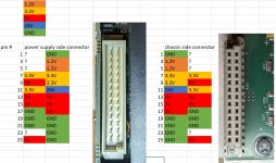
CLX_CHASSIS_PINOUT1.jpg
 
I have just been probing a 1756-PB72 with a multimeter.

I forgot to mention that I have bonded all the commons of the power supplies together. All the commons on the Allen Bradley power supply are connected together to ground.

The 4 pins that I haven't figured out seem to be floating.

I have found that the 1.2V is required for the backplane communication. The cards will power up without it, but they have a backplane communication fault.

So far, I'm not sure what the 3.3V is used for, it makes no difference if I have it connected or not.
 
I figured out my problem, My 5v power supply had too much voltage sag when the other modules were powering up. I couldn't see it with my multimeter but I could with my scope.

For anyone's future reference, I can confirm that the wiring diagram works.
 
I figured out my problem, My 5v power supply had too much voltage sag when the other modules were powering up. I couldn't see it with my multimeter but I could with my scope.

For anyone's future reference, I can confirm that the wiring diagram works.

Nice work MacGyver! And welcome to the forum!
 
I figured out my problem, My 5v power supply had too much voltage sag when the other modules were powering up. I couldn't see it with my multimeter but I could with my scope.

For anyone's future reference, I can confirm that the wiring diagram works.

Nice, thank you for the information. I'm positive that this will come in use in the future. :geek:
 
Thankpad,
Now if you could figure if there is a communication protocol and what protocol is on those 4 other pins, you would really be on to something. With info on the backplane protocol, it would be possible to build a smart power supply that could actually talk on the backplane. I have wanted one of those forever....
 
You could probably build a sort of breakout cable with header connectors so you can use an AB power supply and put a scope on those unknown pins just to see if anything is happening. As far as I know, they don't communicate but you never know...
 

Similar Topics

So I decided to build a very simple PLC to put all my knowledge into one fun project. The question I'd like to throw out there relates to the real...
Replies
3
Views
1,828
Hi! My friend is an electrical technitian who wants to know if it's possible to build a DIY memory cartridge with an EEPROM for use in S7-200 PLCs...
Replies
0
Views
1,149
Hi everyone, I'm looking at a project that will require operator intervention to "simulate" valve/motor feedbacks and analog values. In googling...
Replies
2
Views
1,949
Hi, I've noticed that CO2 controllers are retarded and sell for 500 $ Can you tell me how I could assemble a CO2 sensing chip, then read the...
Replies
16
Views
3,989
Hello everyone. I have been in the electrical trade for close to forty years. I have done basic programming but now have a need to go further. I...
Replies
18
Views
3,279
Back
Top Bottom