Does anyone have experience with a 1746-FIO4V?

Join Date
May 2017
Location
Regina
Posts
12
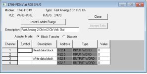
I migrated a SLC500 rack that was RIO to a PLC5 processor. It is now on a 1756-L73. I got confused by the setup of the card and thought it was unused. How would I make to logic to use this card? I really only need the analog input for now but of course I would like to set up the entire card.

TIA
 
On systems like this, it's worthwhile to take some time each morning to sing your own version of "Lord, Won't You Buy Me Some POINT I/O", which I think was originally written by Woody Guthrie.

The good news is that these SLC-500 Analog modules were built in the era where SLC data table memory was precious, so they aren't very complicated.

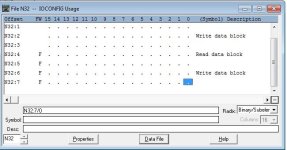
There is no "configuration" file you need to send to the module, only those two words of Output data.

Get the User Manual:
https://literature.rockwellautomation.com/idc/groups/literature/documents/um/1746-um009_-en-p.pdf

The physical setup is simple; all you have is some onboard DIP switches to configure the Inputs for voltage or current mode. The Outputs are both Voltage mode (FIO4V) on this module; you need an FIO4I for Current mode outputs.

The scaling is the only hard part.

The user manual does a pretty good job of showing you the millvolts or milliamts per integer count and that the first couple of bits of the data word for the Output are unused; see the diagrams on Pages 32-35.

For the Input, you can just run a repeating BTR instruction and scale the value as appropriate in your ControlLogix program.

Page 33 of the user manual shows you the resolution for different Analog Input ranges. The module is only capable of 12 bit resolution (0-4095) at best.

okay thanks. I think I have it figured out.
 

Similar Topics

Hi all, Client called saying that the turbidity readout on the HMI is 0.0000 but on the local readout, it shows an actual value. Sure enough...
Replies
12
Views
5,418
Hey guys, Part of the project I'm working on currently is a remote RTU system that is made by Data-Linc; the remote RTU is a CIX-6430 and the...
Replies
12
Views
3,033
Hello folks, Is this the right forum for HMI related questions? We are not using a PLC in our HMI, but a data logger. Looking for peoples...
Replies
2
Views
1,714
Replies
2
Views
1,745
They are installed in a control panel that was made in France and are intended for the termination of analog inputs. Each of the red capped...
Replies
4
Views
421
Back
Top Bottom