HELP PLZ!!Reading Analogue channel of FX2N-4AD

mian

Member
Join Date
Oct 2013
Location
london
Posts
20
Hi friends,
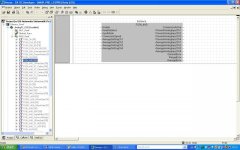
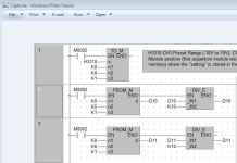
I want to read voltage in the range of +10/-10V using analogue unit Mitsubishi FX2N-4AD with FX1N-40MR. I am using the GX IEC Developer. I have made the programme attached below. I have tried to read from channel1 but i was getting "0". I am supplying the voltage from the power supply.
Can anyone be please kind enough to point out my mistake.
Thanks in advance :)
Capture.PNG
 
Hi Mian,

The Problem is that you use the init (M8002) for reading the value on Channel 1 and 2.
You have to read continuous. You can change M8002 with M8000 in NW#2

But you shoul be carefull by using the DIV, if D10 is "0" then your PLC will go in Error. So make a logic to control for D10 is > 10 before you DIV with 10.

Also the data you will revice in D10 will be a value betwen -2000 - +2000, where -2000 = -10V and +2000 = +10V. 0V = 0

If you have diabled the CH2-4, the you can erase the NW#3

Last thing. you have no errorhandling, averaging of signal etc. You should consider doing some of that to.


/Dariusch
 
Last edited:
Hi Mian,

The Problem is that you use the init (M8002) for reading the value on Channel 1 and 2.
You have to read continuous. You can change M8002 with M8000 in NW#2

But you shoul be carefull by using the DIV, if D10 is "0" then your PLC will go in Error. So make a logic to control for D10 is > 10 before you DIV with 10.

Also the data you will revice in D10 will be a value betwen -2000 - +2000, where -2000 = -10V and +2000 = +10V. 0V = 0

If you have diabled the CH2-4, the you can erase the NW#3

Last thing. you have no errorhandling, averaging of signal etc. You should consider doing some of that to.


/Dariusch

Hi Dariusch,
Thanks alot for your reply.
1. I have tried with continuous scan M8000 as well but no luck.
2. I tried it by turning all the other channels off except channel 1 like [H3330] so i erased NW#3.
3. Initially i checked it by giving 5V from power supply so the calculations will be like +10V=+2000 so +5V=+1000V then by dividing +1000V by 10 i should get +100V ( not exactly +100V due to noise factors etc, i might be possibly wrong so plzz correct me if u think so) but i got "0" instead and sometimes "7"(donno why "7")
4. Sorry i don't know much about error handling and averaging of signals etc. Is it just for a good practice or a compulsory step to read data. I will appreciate your guidance in this regard.
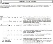
I copied the sample program attached given in the manual as well but no luck.

The problem is that i am still getting "0" in my data register. I have connected my voltage from the power supply to +V and -V of the channel one.

Looking forward to hearing from you or anyone who can help me with this.
Thanks

Capture12.JPG
 
Hi Mian,

Try to use the FB from this library.
When installed the use the FB called FX2N_4AD

I cannot attach big files, so try to find link for you to download the helpfiles etc. for the lib.

/Dariusch

EDIT:

You find what you need here:
http://www.beijer.dk/web/web_dk_be_dk.nsf/docsbycodename/filearchive?OpenDocument&mylink=/web/BexFilePileAUT.nsf/fm.be.searchframe?Openform&Lang=DK&DocID=8ECBFD25199231D1C125728E0059CC59

You have to register, but it is free and you will revice a link to download the files you need.

Mian1.jpg
 

Attachments

  • AnalogFX_V320.zip
    216.8 KB · Views: 51
Last edited:
Hi Mian,

Try to use the FB from this library.
When installed the use the FB called FX2N_4AD

I cannot attach big files, so try to find link for you to download the helpfiles etc. for the lib.

/Dariusch

EDIT:

You find what you need here:
http://www.beijer.dk/web/web_dk_be_dk.nsf/docsbycodename/filearchive?OpenDocument&mylink=/web/BexFilePileAUT.nsf/fm.be.searchframe?Openform&Lang=DK&DocID=8ECBFD25199231D1C125728E0059CC59

You have to register, but it is free and you will revice a link to download the files you need.

Thanks a lot. I spent weeks to learn what you just taught me in one day.
This program is open right in front of me. I downloaded it from Beijer website.
I managed to find the FB file for the FX2N-4AD and tried it on friday but no results. I am just thinking that there might be problem with the device then as there seems nothing wrong with the programming. I tried the same programming with little changes like in connection and [H3310] using the FX2N-4AD-TC for J, K thermocouple and thats working fine.

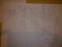
One more thing please. In case the analogue unit is faulty, I have also come up with a circuit consisting of A/D converter to convert my voltage into digital and then amplifies it to 24Vdc to use with FX1N-40MR directly instead of using the analogue channel. The circuit is working fine and the digital output of the circuit feeds into the digital input of the FX1N-40MR. I have tried that as well and i used the function [M8000]----[K4X0 D0] but i got no value in D0
I also used [M8000]----[K2X0 D0] but again no results. I used simple ladder logic like [M8000]----[X0]----{Y0} , [M8000]----[X1]----{Y1} and so on but it doesn't read the inputs i.e 1's and 0's in this case. Can you please help me with this.
Thanks again!!

DSC_0800.jpg
 
Hi Mian,

1. Is there any fault/error on the PLC?
2. Is the FB in a program that is executet?
3. Is there any errorstatus from the FB for the 4AD?

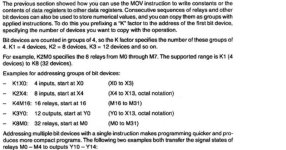
You can use the move to read the inputs from X0-X??.

LD M8000
MOV K4X000
D0
END

Have you connected the S/S-terminal to 0V (if you are PNP-wiring)??

Can you maybe upload your program here?

/Dariusch

There was no error coming from FB when i compiled and downloaded it but it wasn't giving any values (i will send you the pics 2moro whn i put it on online monitoring mode)
I used the exact code
LD M8000
MOV K4X000
D0 according to the manual attached.
As i wanted to read from X0 to X7 so i used
LD M8000
MOV K2X000
D0 it wasn't reading the inputs either.

I WILL CAREFULLY LOOK TOMORROW THAT THE S-S IS CONNECTED TO 0V LIKE the diagram in the manual attached HERE and will update you on the result.

Thanks so much for you help :)
Best Regards,
Mian

Capture32.jpg Capture33.jpg
 
on your attachment you using IC 74LS07 if i not mistaken (+5V) this IC is sink output type go to X1~X7

this means your FX1N-40MR must wiring on NPN.

then 24V via S/S -> X1 then go to 74LS07 Pin 4.

what the minima voltage for digital input on FX1N-40MR can accept?
 
Hi Mian,

Try to use the FB from this library.
When installed the use the FB called FX2N_4AD

I cannot attach big files, so try to find link for you to download the helpfiles etc. for the lib.

/Dariusch

EDIT:

You find what you need here:
http://www.beijer.dk/web/web_dk_be_dk.nsf/docsbycodename/filearchive?OpenDocument&mylink=/web/BexFilePileAUT.nsf/fm.be.searchframe?Openform&Lang=DK&DocID=8ECBFD25199231D1C125728E0059CC59

You have to register, but it is free and you will revice a link to download the files you need.

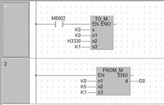
Thanks for your help Dariusch. I have been able to read the channel 1 using the program below. But only when i go to DEBUG --> BUFFER MEMORY BATCH AND THEN BY PRESSING START MONITOR. I get the right values but in address 00009. I don't understand why address 9 as i have D0 in the program. D0 is still 0 when i check it using Monitoring Mode(SHIFT+ESC). I have tried changing D0 to D9 but still it shows zero using the Monitoring mode(SHIFT+ESC).

QWER.JPG
 
Hi Mian,

Try put this code between NW#1 and 2

LD M8000
TO K0 K1 K8 K1
This is writing K8 to the BFM 1. It is the number of samples read from the AD before averageing to BFM 5.

If that does not work, then try this.

Try to change the "K5" (n2) in the "FROM_M" instruction to "K9".
You will be able to read the current value from the input

The BFM "5" is the avarege value for CH1 and the BFM "9" is the actual value for CH1.


/Dariusch
 
Thanks a lot. I will try this in lab tomorrow. Hopefully it will work. After reading different samples of current and voltage, i want to multiply them and carry out out the power (power spikes) calculations like X(n)-X(N-1)/Ts and then compare it with standard voltage to get the spikes in the power. Can i use E-Designer to get graphs and analyse data like compare with the standard voltage. I thought MX Sheet will be a good idea but its very expensive.
Any suggestions please.
 
Hi Mian,

There is averaging as default with BFM #1 and BFM#5, but you can do it like you write.

E-Designer is not actually the best thing to do analyses with.
You can log data down to 1sec, so already here we have the first issue.

I think you should look around for a solution with a sql-server to collect data etc.
I do not have so much knowledge about that, so best if you start a new thred for this.

/Dariusch
 

Similar Topics

Hi Can I get the programming software and data cable name for allen bredly servo drive which model is 2098-DSD-020x?
Replies
4
Views
2,225
I need some assistance to any Siemens Gurus' who can help me convert the following from STL to Lad. I have tried all the old tricks I can...
Replies
4
Views
4,311
Any body here to help me regarding S7-300
Replies
4
Views
1,358
hey evry one i have this problem In the system with S5 CPU 927 it is work ok, but i try to run another four CPU 927 for backup but no one of the...
Replies
10
Views
3,902
sir plz tell me how to interface servo motor with abb micrologoc 1400b plc plz give me detail of instruction and wht type driver may i use or tell...
Replies
5
Views
2,515
Back
Top Bottom