I/O buffering technique for Controllogix asynchronous I/O update

unsaint32

Member
Join Date
Oct 2012
Location
minneapolis
Posts
365
I am having a hard time understanding how using a reference tag (a buffer) would prevent the I/O value changing in the middle of a program execution. The following is an excerpt from LCX5K manual.

"Follow these steps to buffer I/O.
1. On the rung before the logic for the function, copy or move the data from
the required input tags to their corresponding buffer tags.
2. In the logic of the function, reference the buffer tags.
3. On the rung after the function, copy the data from the buffer tags to the
corresponding output tags."

I am attaching two pictures. 0.jpg is without buffering. 1.jpg is with the buffering (the way I understand it).

In 0.jpg, asynchronous I/O updating could make both O:0/0 and O:0/1 turn ON at the same time because I:0/0 can be updated when the processor is in-between the two output rungs.

But even with the "buffering," can the value of B3:0/0 be updated in-between the two output rungs, just as I:0/0 could, therefore producing the same result?
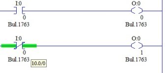
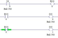
0.jpg 1.jpg
 
No, B3:0/0 will only be updated once per scan. The rung has to be scanned for it to update, as long as you are not using that address somewhere else.
 
I'll try and explain this.

In 0.ipg you mentioned that O:0/0 and O:0/1 could turn ON at the same time. Not Necessarily. Due to the asynchronous nature, depending on what part of the scan the logic is executing it could be at the beginning, middle or end of the scan, the results vary. Say for example it happens to be at the beginning of the scan and the Data table for I:0/0 happens to be true then O:0/0 will turn on, and then say the data table value after some time gets changed back to false and then to true before even the logic has a chance to see that change that took place that can have undesirable results. So at that point you kinda don't have full control of what comes on and when, but more so the scan does.

Now in your 1.ipg where you use the buffer here is the difference. The B3:0/0 buffer is their because now, you will be absolutely sure that the input went true or false, and you won't miss the data table values updated more than once before the logic has a chance to see it. More so if I:0/0 turns on whatever point it may be in the scan, it will eventually turn on B3:0/0, and if I:0/0 turns off again depending on when the logic gets to see it B3:0/0 will turn of.

In conclusion the concept to understand is that if you don't use buffers you risk the chance that I:0/0 goes true or false before the logic has the chance to see it. If you use the buffer in your logic now you don't have to worry about missing the transitions of I:0/0 value because B3:0/0 will update only once per scan and will hold a value up until the next time the logic sees the change in input.

Finally to answer your question, no they won't produce the same result

Hope this helps.
 
Last edited:

Similar Topics

Hi guys, I am new to the forum and Rookie PLC Programmer. I did start programming a bit of RsLogix500, Studio 5000 and Step 7 V16 and still...
Replies
7
Views
1,714
Hi all I have a project to convert a Micrologix1500 with onboard IO and IO extension modules to a Compactlogix 5069_l306ER with 2 local 16point...
Replies
4
Views
2,626
I have always used mapping to buffer IO to avoid random program hiccups caused by changing inputs in the middle of a program scan. Now I am doing...
Replies
8
Views
4,043
I've got a system that consists of a A-B ML1500 with a bunch of thermocouple input cards. The PLC is located in a nasty environment, smoke, heat...
Replies
6
Views
3,324
Traditionally I create buffer routines to read all inputs into a new tag, and conversely, the output buffers to the actual output tags. However I...
Replies
4
Views
2,589
Back
Top Bottom