LogixPro Advanced Batch Ex. 2 Question - Progress Included

jcvictory

Member
Join Date
Oct 2021
Location
Wilm
Posts
2
Good morning,

I am currently working on the LogixPro Advanced Batch #2 Multiple Mode of Operation and got stuck very close to completion. Link below for exercise details and program attached.

https://canadu.com//lp/doc/bl/bl-adv.html

Everything works properly except I cannot control both the batch count number and the mixture % of pump 1 with the thumbwheel. I can do either batch count or % but not both sequentially.

The counters being controlled are C5:2 (batch count) and C5:0 (mixture % pump 1). The address for the thumbwheel is I:3

I tried using I:3/1 and I:3/2 for the source of my Convert to BCD (FRD) bit but found they are still the same address.

Is what I am trying to do possible with 1 thumbwheel input? I could easily do it if I could switch from selector switch B for batch count and selector switch C for percentage but my interpretation of the instructions says use B only. Hopefully this question made sense to someone.

General constructive criticism of my code is also welcome.

Thanks, 🍻
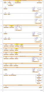
ADVANCED BATCH 2.jpg
 
Last edited:
First, let me congratulate you on actually coming in with written code and a question on a specific aspect of it... a breath of fresh air compared to a couple other recent threads asking for help.

I tried using I:3/1 and I:3/2 for the source of my Convert to BCD (FRD) bit but found they are still the same address.
The FRD instruction operates on an entire 16-bit word. If you are trying to give it individual bits you are failing to understand its function.

Is what I am trying to do possible with 1 thumbwheel input?
Only if you can use something else to tell the program which counter to put the thumbwheel value in.

I could easily do it if I could switch from selector switch B for batch count and selector switch C for percentage but my interpretation of the instructions says use B only.
The ideal [real-world] solution imo would be to add a second enter pushbutton or selector switch.

I would think you could use position C if adjusting the mix on-the-fly was prohibited (ie they had to stop it to change value anyways), but the instructions don't indicate one way or the other.

You could kluge something regarding length of enter PB press or the like, but imo that would be problematic vis-a-vis the instruction to keep the interface "as simple and fault tolerant as possible."

tl;dr I don't see a great solution unless you've got an extra input lying around unused.

General constructive criticism of my code is also welcome.
On rung 13 the OSR should use an otherwise unused bit address. You seem to currently be using an address from I:3, meaning whether the rung works the way you expect will depend on the thumbswitches' value...


Your controls for the fill ratios seem problematic:

I don't see any method to adjust the amount coming from line 2, just line 1.

It looks to me like currently Pump 1 will pump a number of units equal to C5:0.ACC (to be set from thumbwheel), but then Pump 2 will pump a flat amount (currently 305 units). If the percentage of mix coming from line 1 changes then the percentage of mix coming from line 2 will need to be adjusted as well (unless you're doing some math beyond just reading in the thumbwheel value).

Is the size of the tank known? If not, then alternating the pumps from each line like this is a good way to end up with an off mix % because the high level sensor comes on at different points in the cycle... (this one's more on the person writing the problem than you; in a real-world mixer you'd either control the actual flow rates to adjust the mix ratio or stop based an amount filled with the high sensor as an overfill safety).

You could reduce issues from this by running the pumps simultaneously, shutting off the line with a lower mix % as needed to adjust the ratio.
 
Last edited:
First, let me congratulate you on actually coming in with written code and a question on a specific aspect of it... a breath of fresh air compared to a couple other recent threads asking for help.

plvlce - Thanks for the detailed response. I read a few posts looking for the answer previous to writing this and saw this was the agreed upon way to do it here. I have another semester of PLC programming coming up so I will likely be back.

The FRD instruction operates on an entire 16-bit word. If you are trying to give it individual bits you are failing to understand its function.

Yes, I will need to look into this more. Saw this used on here and mimicked it here without fully understanding.

Only if you can use something else to tell the program which counter to put the thumbwheel value in.

The ideal [real-world] solution imo would be to add a second enter pushbutton or selector switch.

I would think you could use position C if adjusting the mix on-the-fly was prohibited (ie they had to stop it to change value anyways), but the instructions don't indicate one way or the other.

You could kluge something regarding length of enter PB press or the like, but imo that would be problematic vis-a-vis the instruction to keep the interface "as simple and fault tolerant as possible."

tl;dr I don't see a great solution unless you've got an extra input lying around unused.

I may just use selector C since it will remain unused anyway. I would certainly rather learn the best real-world way to do this. Just wanted to make sure I wasn't missing something obvious.


On rung 13 the OSR should use an otherwise unused bit address. You seem to currently be using an address from I:3, meaning whether the rung works the way you expect will depend on the thumbswitches' value...

This address was left over from the first exercise and just now realize it shares the address of the thumbwheel, thanks. Originally, I did not even have the OSR in this rung. The resets were all controlled by the C5:1/DN bit but at higher scan rates they were not working for some reason. Any clue? Is the OSR necessary here?

Your controls for the fill ratios seem problematic:

I don't see any method to adjust the amount coming from line 2, just line 1.

It looks to me like currently Pump 1 will pump a number of units equal to C5:0.ACC (to be set from thumbwheel), but then Pump 2 will pump a flat amount (currently 305 units). If the percentage of mix coming from line 1 changes then the percentage of mix coming from line 2 will need to be adjusted as well (unless you're doing some math beyond just reading in the thumbwheel value).

Is the size of the tank known? If not, then alternating the pumps from each line like this is a good way to end up with an off mix % because the high level sensor comes on at different points in the cycle... (this one's more on the person writing the problem than you; in a real-world mixer you'd either control the actual flow rates to adjust the mix ratio or stop based an amount filled with the high sensor as an overfill safety).

You could reduce issues from this by running the pumps simultaneously, shutting off the line with a lower mix % as needed to adjust the ratio.

I had a feeling this portion was going to be brought up after reading some of user: Lancie1 's posts on the pumps running simultaneously. I wanted to get it working first so I could get my grade recorded for class, but challenge accepted.

You are correct about Pump 1, but Pump 2 simply ran until the hi-level sensor went true after Pump 1 counter was done. I agree with what you said above and it did feel naughty to use a safety sensor as a normal part of operation. The total tank volume is 306. The 305 you mentioned was for Pump 3 emptying the tank, where I had problems controlling the restart operation at 306 for some reason. The lo-level was not co-operating. So, I had 1 unit left over each time the batch started over. Will try and fix that as well.
 
I would certainly rather learn the best real-world way to do this. Just wanted to make sure I wasn't missing something obvious.

I don't think you particularly missed anything. As I mentioned, if mix % is assumed not to change during process than using position C seems quite reasonable, as operator would then have to switch back to B before running.

If it does need to be changed on the fly, there's potential issues with operators leaving the switch in C, you have to account for potential that switch momentarily does not read any position when switching, etc.

This address was left over from the first exercise and just now realize it shares the address of the thumbwheel, thanks. Originally, I did not even have the OSR in this rung. The resets were all controlled by the C5:1/DN bit but at higher scan rates they were not working for some reason. Any clue? Is the OSR necessary here?
The OSR prevents the RES (and the one OTE) from remaining true if C5:1/DN is true for multiple scans in a row.

The DN bit will only be true at that rung during the following scan if, when the CTU instruction is next evaluated, the ACC is >= the PRE.

Since C5:1 is one of the things reset, this happens under only two conditions:
1) If the PRE is 0 or less it will always happen
2) If the PRE is 1 and the CTU is triggered (ie I:1/7 is true).

If you can guarantee neither of those will be the case, then the OSR becomes redundant. If not, you need either an OSR or other logic accounting for the situation.

I had a feeling this portion was going to be brought up after reading some of user: Lancie1 's posts on the pumps running simultaneously. I wanted to get it working first so I could get my grade recorded for class, but challenge accepted.

You are correct about Pump 1, but Pump 2 simply ran until the hi-level sensor went true after Pump 1 counter was done. I agree with what you said above and it did feel naughty to use a safety sensor as a normal part of operation. The total tank volume is 306. The 305 you mentioned was for Pump 3 emptying the tank, where I had problems controlling the restart operation at 306 for some reason. The lo-level was not co-operating. So, I had 1 unit left over each time the batch started over. Will try and fix that as well.

If the total volume to be pumped is known then a number of my criticisms are less valid. It just seems strange to me to be pumping a known amount and yet have the instruction specify "The tank is to be filled to the point where the Hi-Level sensor goes true." Why say it that way if the sensor is intended for safety against overfilling? It's technically true, but makes it sound like you're using the sensor to determine the amount being pumped.

Having both pumps running simultaneously should not be significantly more difficult than running separately and is definitely more realistic to most real-world applications as it saves time (and, as they say, time is money).
 

Similar Topics

Hi all...long time lurker, first time poster. To make a short story long, I'm retired Navy (March 2000) and had never heard of a PLC prior to...
Replies
5
Views
4,370
Hello to the PLC forum, I have a question on the excellent Logixpro Simulator. Im trying to complete the more advanced Traffic Light simulator and...
Replies
7
Views
3,985
Hello everyone . I'm just a PLC beginner and using Logixpro as a training software . Now I'm beginning the problem of bottles conveyor belt but I...
Replies
0
Views
1,520
SELECTED NEW FILE SELECTED PROCESSOR TYPE SELECTED I/O CONFIGURATIONS IM UNABLE TO CONFIGURE MY I/O’S. I HAVE A PAPER COPY OF A PROGRAM AND I...
Replies
0
Views
81
Hi folks, i'm pretty much new on this topic and i need some help with the dual compressor part 3 and 4, currently working on part 3 i cant make...
Replies
20
Views
5,115
Back
Top Bottom