Micrologix 1400 Embedded IO Map

glenncooper

Member
Join Date
Oct 2010
Location
Vermont
Posts
24
Hello...I'm a pretty fluent SLC 500 programmer, but am now trying to develop a Micrologix 1400 program offline (1766-L32BWAA). I'm amazed that I haven't been able to just go somewhere in one of the manuals to see where the embedded IO maps. Obviously it maps to O:0.x for outputs, I:0.x for inputs - but where, exactly? From other posts I found a somewhat buried reference to the embedded analog IO mapping to I:0.4 through I:0.7 for inputs and O:0.4 through O:0.5 for the two analog outputs. That solves the analog part.

I'm guessing (and I HATE to guess) that the embedded discrete I/O will map at word 0 for both input and output. BUT...This leaves assigned IO that I can't find documentation on.

In the case of the inputs I have 4 input words available I:0.0 - I:0.3) but I only have less than 2 words (20 bits) of discrete inputs to address. In the case of the outputs I also have 4 words available, and only need 1 word (12 bits) to address the outputs.

This should be such a simple thing to have documented by A.B. - maybe I'm just missing it....

Does anyone want to take a crack at just telling me what the I/O map is - or pointing me to an appropriate resource that documents this? - Many thanks!
 
For some reason more than the physical I/O are shown on the Micrologix I/O data tables. I don't know why. I ignore those not physically present. I have found no reference. I assume it must have been easier to write the software that way. I know, not much of an answer.
 
All of the Micrologix controllers do this ( show extra addresses). I don't know why either, hopefully Ken will check in and give us the inside story.

The ML1000 shows the extra addresses as (Reversed).

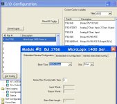
It will help if you configure the base you are using under I/O config. ( See Picture below.
Then take a look at the wiring diagram for your base and take note of how the
inputs and outputs are labeled.( see picture below)
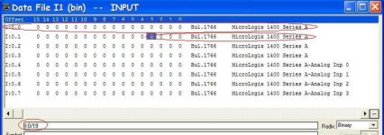
Then open the data tables ( input and output) and start counting from the first one (I:0/0-O:0/0 )( see picture below ) take note of there addresses, those are your embedded I/O.
In your case you have the first 20 inputs 0-19 and the first 12 outputs 0-11.

Hope this helps.

ConfigBase.jpg WireDia.jpg inputdatatable.jpg outputdatatable.jpg
 
Last edited:
The additional words are diagnostics bits assigned to each Input or Output

I have seen it documented and will try to find it, will post if I find it.

My understanding of it is,
I have told the bit to turn on please send a message back that you have done so.
 
Thanks to everybody for your responses. It gets me out of my "stuckness", and gave me the reassurance of knowing that I'm noy TOTALLY crazy - at least not yet... I generally really like A.B. Products, but am often left scratching my head about why they do what they do. I guess we can call it job security!
 
Analog I/O with Micrologix 1400

I also am developing a program offline and understand the digital I/O structure, but I'm having some difficulty with the on-board analog and with the add-on analog addressing. Does anyone have any experience with the analog mapping. I have an external 1762-IF2OF2 card installed in slot 5. Thanks for any assistance anyone can give.
 
Okay. For instance, would the 1st and 2nd analog input words on Slot 5 be: I:5.0 and I:5.1 for the two analog inputs, and O:5.0 and O:5.1 for the analog outs? If this is correct, what is the addressing for the on-board analog? Thanks
 
1st and 2nd analog input words on Slot 5 be: I:5.0 and I:5.1 for the two analog inputs

Yes those are the addresses

O:5.0 and O:5.1 for the analog outs? If this is correct

Yes

For the base units analog addresses see picture "inputdatatable in my post #3 above.
 
Regarding the on-board analog addressing -

Page 30 of the reference manual spells this out for inputs:

The MicroLogix 1400 -L32BWAA, -L32AWAA, and -L32BXBA support
4-channel, 12-bit resolution analog input with four 12-bit resolution
analog input channels. These channels are single-ended (unipolar) circuits
and accept 0…10V DC.
Input words 4…7 contain the value of analog inputs (Word 4: analog
input channel 0, Word 5: analog input channel 1, Word 6: analog input
channel 2, Word 7: analog input channel 3).


And page 32 for outputs:


The MicroLogix 1400 -L32BWAA, -L32AWAA, and -L32BXBA support
2-channel, 12-bit resolution analog output. These channels have 0…10V
DC output range. Output words 4 and 5 contain the value of analog
outputs (Word 4 : analog output channel 0, Word 5 : analog output
channel 1).
 
Last edited:
For the IF2OF2 card you might also want to refer to the A.B. installation manual, which identifies the I/O mapping. Since some analog input cards use the corresponding output data table for configuration it wasn't necessarily a given that the analog outputs would map to words 0 and 1 of that corresponding slot, but the do. I just did a quick google search on "1762-IF2OF2 literature" to get right to the A.B. page I needed.
 

Similar Topics

I have a new Micrologix 1400. I have an SCP instruction that should give me a 0-4095 output on O:0.5 address. Problem is it does not ever change...
Replies
11
Views
2,846
Howdy all, New to the 1400. I have read the manual a few times (maybe not every word) but still can not find where the embedded discreet inputs...
Replies
13
Views
13,004
Hey all, first time poster here. I am wondering if anyone has tried using a Keyence SR-X300 barcode scanner to a Micrologix 1400. Keyence sent...
Replies
0
Views
32
I'm using a SLC typed write from the ControlLogix5572 to the MicroLogix 1400, with path: 2, (MicroLogix IP). The ControlLogix equipment has a...
Replies
0
Views
95
Hi, I am working with a Micrologix 1400 model 1766-L32BXB. With no input wires connected to the “in12” thru “in19”, I am getting 24 volts while...
Replies
4
Views
223
Back
Top Bottom