Mitsubishi: What does + and MOV do?

Mas01

Member
Join Date
Oct 2020
Location
Leicester, England
Posts
1,109
Hi, can anyone help? Complete novice here GXDev/SoftGOT/GTDes3


I've had a question from a colleague asking me 'how does the PLC calculate the motor power?'. I know from our GTDes3, that on the PLC main screen, motor power is displayed by outputting the value of D46.


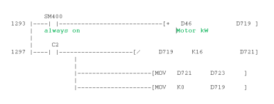
So then I looked at the GXDev ladder and this is how D46 is calculated [see pic], but I don't understand what's going on.


On line 1293, is D46 added D719?
On line 1297, is D719 divided by 16, and the result put in D721?
I'm not sure what MOV does (intuitively it MOVES a value?)


Any help appreciated. Thanks
Capture3.PNG
 
Just in case it's useful, the next rung down is:

...............C2
1305 |-----| |----------------------------------------------[RST C2 ]
 
Last edited:
The + instruction adds the value in D46 to D719 then stores the result in D719
On Counter 2 (Count value reached so there will a rung somewhere where it is counting up like and something out C2 Kxx xx being a pre-set for the counter
D719 is divided by 16 and the result is stored in D721.
on the count value being reached D721 is moved to D723 and then zeros D719
It looks like it is accumulating the motor Kw, dividing it by 16 then on a count it stores it and resets the accumulated value in D719.
And to stop it doing it again, counter 2 resets itself so this is effectively a one shot and only happens for one scan when the counter reaches it's value.
That's really useful, thanks.
Doing a cntrl-F on the ladder, There's only one occurrence of D46 in the whole logic (i.e. only on line 1293). I'm unclear on how D719 gets its value if D46 is (I assume) an output.


Let me try and find out more about D46 and D719.
Many thanks.
 
D46 could be a value set by some analogue input or from communications or from the HMI as a pre-set or even stored initial value i.e. set during programming (this would have to have the parameter set in the parameter file as retentive.
If from an analogue then an instruction to fetch the channel data from an analogue card only will reference the first Data word so for example if the 4 or 8 channels from an analogue card were transferred to D42 then all channels from 0 to 4 (or 8 if 8 way card) would be transferred to D42-45 or (49). so it is possible there is no other cross reference. There is one other possibility that the use of indirect addressing putting a value into D46. for example if the index register (Pointer) is used a transfer to D40Z0 will move data from somewhere into D40 + the offset address in Z0.
without seeing the whole program plus the plc parameter settings & HMI files it is impossible to say.
 
So helpful, parky.
I'm digging into various files, I can see in a spreadsheet that D46 is indeed an analogue input/wire (on a Q68AD-G 8x current/voltage input card)from the motor control cabinet.


The input range is 4-20 mA.
 
Last edited:
Yes there will be an instruction Ux\Gx to read in the data sometimes this is done as single instructions or as a complete bank, however, on latest models the IDE can configure the modules in a utility program therefore there may be no cross reference to how the data is transferred into Data Memory.
 
Yes there will be an instruction Ux\Gx to read in the data sometimes this is done as single instructions or as a complete bank, however, on latest models the IDE can configure the modules in a utility program therefore there may be no cross reference to how the data is transferred into Data Memory.
Yes, there is. I found this under Program|ANALOGUES in GXDev:
X110 is 'Module Ready'
Edit: Another piece of info - this comes from 'rack 1 slot 1' (analogue card)
I think this means: If buffer memory 10 bit 6 is TRUE and BFM 49 bit 6 is not set, MOVe BFM G17 into D46.

Capture4.PNG
 
Last edited:
Those bits are probably diagnostic bits from the card I do not have a list of the Buffer memories handy but probably will only be true if the conversion is ok or enabled.
10.xx is AD conversion completed flag I believe.
And 49.6 is Error detection for that channel
 
Those bits are probably diagnostic bits from the card I do not have a list of the Buffer memories handy but probably will only be true if the conversion is ok or enabled.
10.xx is AD conversion completed flag I believe.
And 49.6 is Error detection for that channel
You've been more than helpful once again.
Thank you for your time and patience with my questions.
 

Similar Topics

Sorry for the basic question... I've had a look through the Q68AD-G (analogue input to digital converter), and I'm trying to find out if the...
Replies
11
Views
3,048
M367 is a press-button on the PLC screen, X212 and X213 are PHYSICAL buttons on a control panel - you press them with your finger. What does the...
Replies
14
Views
2,164
GTDes3, On all the tabs where the HMI screens are defined, each tab contains the words "(Front+Back)". Anyone know what this means? Thanks
Replies
1
Views
1,165
I've got a bunch of alarms in GT designer3 and they are "mapped" to M parameters, eg M277. What does M signify? Thanks
Replies
4
Views
2,260
Back
Top Bottom