My First program! and I need a little help

CKYDMK

Member
Join Date
Dec 2011
Location
Ontario
Posts
5
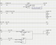
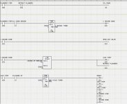
I was given a small PLC project from my dad for his company and I have ran into a few problems. I have found it necessary to use an output in my program more than once, so I made up subroutines to accomodate for that seeing as I cannot do it in the main program. But my main concern is when I download the program to the PLC, it does nothing. Absolutely nothing. I'll be the first one to say I have no experience other than in school and that was 2 years ago and even then my teacher walked us through the programs.

I've attached the program and a sequence chart that I made up. I have tried to troubleshoot this for a couple days now and I just KNOW its going to be something quite simple but yet something that I am unable to find because I lack the knowledge. I would greatly appreciate any help, and if I have broken any rules by all means remove this post.

Thanks in advance
Untitled.jpg Untitled2.jpg Untitled3.jpg Untitled4.jpg
 

Attachments

  • sequence.xls
    10 KB · Views: 32
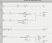
I'm sorry that i don't know this PLC but there doesn't seem to be an instruction in the Main section to invoke the subroutine. It probably would be unconditioned. I like that you have identified and executed states then used those states to trigger the appropriate outputs. For consistency you may wish to place the 'Cylinder Down' output in the 'Output' subroutine.
 
Last edited:
Is what is shown in the four jpg pictures the entire program? Please post the brand and type plc along with the name of the programming software. Zip and post the program.
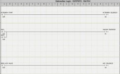
Part of the ladder seems to be missing in picture #3. Does it include the (R) outputs for (S) S32 and (S) S35?
 
Last edited:
CKY,

I think you do not have a Main with 4 Subroutines, but 1 program with several steps. You can do this without so many of the S Relays.

I see some errors, and there are probably many more. Here is a short list.

Pictue File 2: You Set S39 "Loop Done", but never Reset it anywhere, so it will be ON forever after the first run. Also, you do not ever reset the LOOP COUNTER by triggereing the S38 "Loop Reset".

Picture File 3: You Set S35 "Last Step", but never Reset it anywhere, so it will be ON forever after the first run. You Reset S21 "Ready", but it was never Set in the first place, so "Ready" will never go ON.

I agree with Bernie that for consistency you should move Output 4 to your Output area (Picture File 4) with the other outputs.

I combined your pictures with your Excel spreadsheet, to make it easier for others to study and make comments.
 
Last edited:
I read over the replies I have recieved (thanks) and I have decided to re-write the program. I have simplified it greatly (I think) and I now have action from the machine! But yet it does some things that I am not too sure of. Outputs 1 and 2 go on and off as soon as Start is pressed and the timers do not seem to do anything. The conditions for the timers to be activated workm but yet they dont count and the outputs do not turn on properly.

I am using an EZautomation touch panel (EZ-S6W series) and from what I've read from here and other sites that these are not the easiest for people to learn on. I have attached a .zip containing the entire program and I hope somebody can open it. :ROFLMAO:

Once again I greatly appreciate the help.

Thank you
Dana
 
Ladder logic converted to pdf file, see attached. I only saw 7 rungs in the file you uploaded, is this correct?
Edit:
For the timer to work I think you need to set a value in R51. In Tag Database, Click on tag 32, VACUUM TIME #1, --> Add/Edit --> Check Initial value --> Enter the value of the time (for instance 5000 for 5 seconds with .001 timebase) --> Apply changes --> Close Tag Details box.
 
Last edited:
CKYDMK,

i would like to suggest that you write the code in such a way
that you use only one output point for your logic. In my opinoin, it is never a good idea to have multiple rungs of outputs for the same point. HOW will you know where it was turned on or turned off?

food for thought.

regards,
james
 
A new version. I am not too sure what is meant by the outputs on one point. Do you mean they should all be in a subroutine or that there should only be one output per rung?
 
As a general rule, you should only have your outputs written once in the program and never put logic controlling real I/O in a conditional subroutine in ladder logic. There are very few valid reasons for doing that. A program as short as yours should be all in one routine.

Take a different approach to writing your logic:

Put the outputs in first, then write the logic in front of each one that should cause them to turn on. Use branches for situations in which there are multiple steps which should trigger the outputs.
 
Put the outputs in first, then write the logic in front of each one that should cause them to turn on. Use branches for situations in which there are multiple steps which should trigger the outputs.
I strongly agree with Paul's steps.

Probably this program needs only a ladder rung for each output, plus 1 rung for each timer. Period.

Get rid of the subroutines, interrupts, and do not use Set and Reset. Use plain old ON-OFF logic for each rung.

(1) Put in all your Outputs and Timers in one main ladder logic routine.
(2)For each rung, ask yourself: What should turn ON this Output (or Timer)? Insert that ON logic.
(3)For each rung, ask yourself: What should turn OFF this Output? Insert that OFF logic.
(4) Test and revise until you get it all working.
 
Last edited:
CKY,

ERROR 1: Looking farther, your Rungs 1 and 2 must have a show-stopping error. You use a I1 NC Door Open Switch to turn on S21. Then on Rung 2, you look to see if I1 is closed (opposite to the I1 in Rung 1). Therefore, in Rung 2, both I1 DOOR and S21 READ can NEVER be ON at the same time, therefore Q1 VACUUM will never be Set to ON.

ERROR 2: If Q1 COULD ever get turned ON, in Rung 3, you Reset Q1 after some time period. Therefore Rung 2 would probably immediately Set Q1 again, and you would have a repeating infinite loop that chases its tail around and around.

I think you need to do some studying about how to use process Step or Stage Relays to step a machine through a series of events, without hanging up and without creating repeating loops that can never end.
 
Last edited:

Similar Topics

Hi all, I am having issues accessing my Cimplicity software - the site code changed after re-install and I am no longer able to attain a new key...
Replies
10
Views
174
Hi all, I’m new to programming and want to write a simple routine. Push start button, turns on sensor. 2 second delay before anymore logic read...
Replies
1
Views
339
I will be designing an automated hydrostatic system. The system on paper works like this, a plc like the click will get information from an hmi...
Replies
227
Views
43,266
Hi everyone, I'm looking for a sample program that has some UDTs defined in it for the MicroLogix platform. To create them, you need to have the...
Replies
6
Views
2,241
Hello. I am working on a PLC program that needs to check input 1 after timer two is complete to see if a valve can close or not. Below is the flow...
Replies
9
Views
2,839
Back
Top Bottom