Welcome to the PLCTalk forum community !
You are correct that A-B sometimes adopts old ASCII printer control terminology, in which Carriage Return (0x0D hexadecimal) is called "Control-M" or "^M".
If you are configuring the Channel 0 serial port to recognize that as a Termination character, enter it in hexadecimal style, which in RSLogix 500 is "\d". That is also the default configuration for Channel 0.
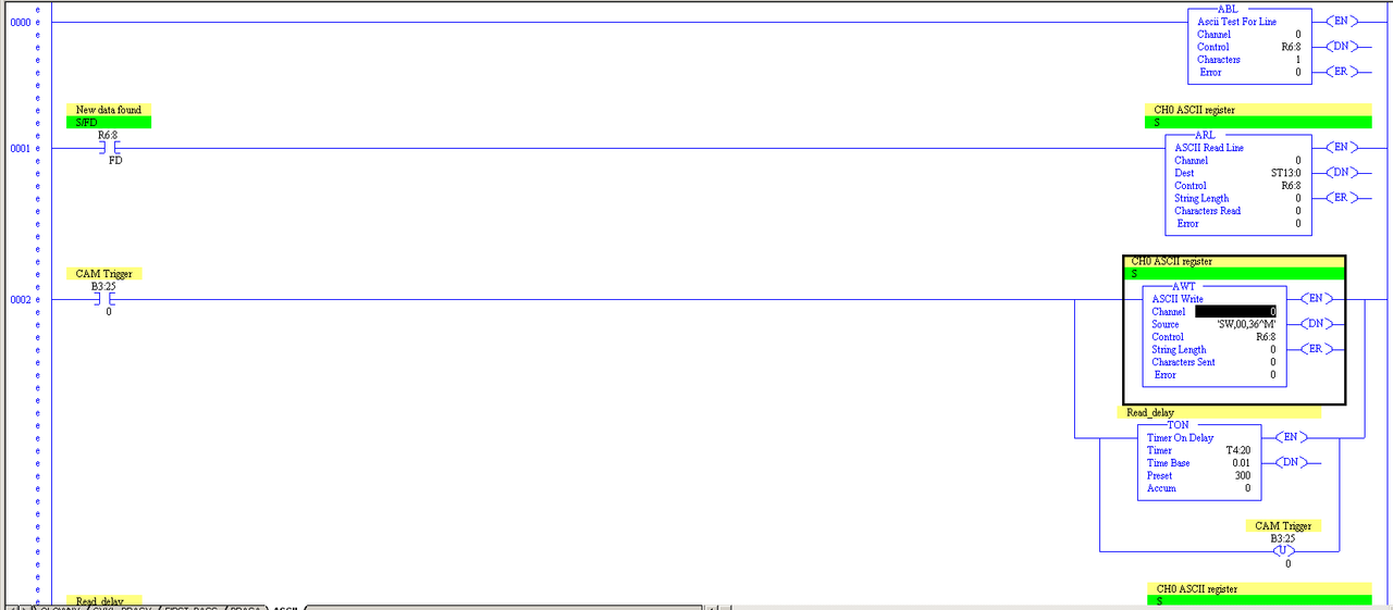
I prefer to use the "ASCII Read Line" instruction (ARL) instead of using one of the buffer-testing instructions (ABL or ACB) or the Read Buffer instruction that doesn't care about the termination character (ARD).
ARL reads a whole "line", which includes the Carriage Return delimiter. Once you execute the instruction (the rung goes from false to true), it waits indefinitely for a "line" to arrive in the buffer. You can write a timeout to purge the buffer on startup or if it's been too long between expected inputs.
As noted, your first ASCII instruction will only execute on the first scan of the program, since it's on an unconditional rung. ASCII instructions are buffered by the SLC-500 operating system and need a false-to-true transition to execute each time.
In addition, be sure to use a unique "Control" element for each ASCII instructions. You're using R6:8 for all three in your screenshot, which will prevent them from working correctly because they will write over one another's status and control bit. Unfortunately, RSLogix 500 does not look for such conflicts and warns the programmer.


") ), when Rung 0000 executes, the ACL instruction will clear all buffers, and the instruction [OTL R6:8/UL] will latch the value of R6:8/UL to 1, both of which will stop the execution of, and de-queue, the ARL instruction, and also assign a 1 to the value of the error bit R6:8/ER (see
), when Rung 0000 executes, the ACL instruction will clear all buffers, and the instruction [OTL R6:8/UL] will latch the value of R6:8/UL to 1, both of which will stop the execution of, and de-queue, the ARL instruction, and also assign a 1 to the value of the error bit R6:8/ER (see