Setting up Traps in PLC to find whats stopping conveyors

stayclashy80

Member
Join Date
Jul 2020
Location
raleigh
Posts
76
Hello everyone,
So I need help setting up traps in Studio 5000. Disclaimer I'm an intermediate PLC programmer so I need lots of help and I need to learn a lot. My initial plan was just to use a one shot based on conveyor running status bit and then a bunch of MOV instructions to send data to newly created storage tags. Problem was I needed bit data not word data and I couldn't use bit data for the MOV instruction. I looked around and found OSR instruction ( one shot rising ) and it said it has a storage bit. I tried this and got scared because the conveyors started having transients so I removed the code. So now I need to know if the OSR actually changes the value of bits or not. I noticed in cross reference it was referenced as "destructive" type. I'm not sure what that means either. Any help would be greatly appreciated.I attached a screen shot of the logic I had in temporarily. Thanks so much. You guys are awesome and always help me out so much.
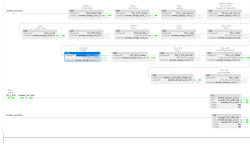
SMN1 trap logic.png
 
What I've done in the past if I have a bunch of bits in series controlling a single enable bit...


Add a rung directly ABOVE the rung that controls the enable bit. The first instruction on the rung should be the ENABLE bit so your new rung is active only when the ENABLE bit is true. Then, have an output branch for each bit that can make the ENABLE bit turn off. If any bit is in a state to stop the enable bit, have it latch (OTL) a LATCH bit. The next rung to be executed will turn off the ENABLE bit, which means that the latched bit will indicate what made the ENABLE bit turn off. If you want a history, have the LATCH bits be part of a word that you MOV to a storage word when the ENABLE bit is re-enabled, right before writing a 0 to the LATCH bit word to get it ready for the next stop.


I may be able to post an example or better description tomorrow.
 
>now I need to know if the OSR actually changes the value of bits or not.

Yes, it does. You correctly understood that it's designated as a "destructive reference", but mis-understand how it works.

OSR is not "take the boolean value from here and store it there".

Instead it is like an ONS oneshot where the only instruction to the right is an OTE to set a single Output bit. The "Storage Bit" is a boolean scratchpad memory location to stash the prior state of the instruction.

What you probably need is an ONS instruction followed by a set of branches with XIC's (the bits you want to store) and OTE's (the subelements in a DINT you want to store those values in).
 
hmm ok i think it get it now. so just so i feel better the code I had written wouldn't be able to change the values of the storage bits correct? I was worried that my section of code was changing the value of all of my storage bits and stopping the conveyor from running.
 
I am pretty sure that code was setting all of the OSRs' Storage Bits (RUN_CONVEYORS, TR2_4_NO_FAULTS, ..., TR2_4_FWD) to the same as the single input bit Jeremiah_Test_bits.8, which is the bit read by the XIC at the beginning of the rung.

The OSRs' Output Bits in the jeremiah_storage_word were all set to 1 on any scan when Jeremiah_Test_bits.8 had a 0-to-1 transition from the previous scan, and all were set to 0 on any other scan.
 
May i make a suggestion.
write out what you are trying to do in english in a step by step manner.
write your code accordingly.
put comments in the logic to explain what you are doing.
i see your rung and in my opinion, you need to make several rungs out of it and document what you are doing. there are so many osr instructions it is getting complicated. while you understand what is going on, others may not. keep in mind that maintenance has to troubleshoot your logic at 1 am when things don't work. if they cannot, you will be the one getting a call at 2 am and have to come in and fix the problem. then you will have to write the code so that maintenance can understand what is going on. having to drive 200 miles one way to a customer site at 2 am is not fun. you get there and in 15 minutes the problem is fixed. drive back (to work, it is now 7 am) and explain to your boss what happened and then have to deal with the issue at 9 am when the customer wants to charge your boss for lost production.
many of us have been there, so work with maintenance and find out their capabilities.
regards,
james
 
... keep in mind that maintenance has to troubleshoot your logic at 1 am when things don't work. if they cannot, you will be the one getting a call at 2 am and have to come in and fix the problem...


I call this "defensive coding". I want to make absolutely certain that I'm NOT the only person in the building who can figure it out. I put comments, comments, and more comments in the code and try my best to put a LOT of details in a LOT of error messages on the HMI. Like, "PROX xyz didn't turn on in time, input YYY" instead of "cylinder abc fault". It really doesn't take a whole lot of extra time but it really pays off in the long run. Remember also that 5-years-from-now-you will have been involved in a LOT of things between now and then. Make it easier on yourself too.
 
Here are a few screenshots from the code I mentioned above. As you can probably tell, the original code was migrated from a PLC2 to a PLC5 to a ControlLogix over the course of a few decades.

The first rung shown is actually one of several with the OTL instructions, broken up to make it easier to read/edit. Note that the input instruction before each respective OTL instruction is the opposite state of the one in the LT_MillRun rung.

The second rung is the actual control rung that turns on LT_MillRun.

The third rung grabs the status of the bits that are in the OTL rung and stores them immediately in a separate place that's displayed on the HMI. This also saves the status of the word because often other things would stop once LT_MillRun drops out making it impossible to tell which thing is the culprit.

The fourth rung clears the OTL bits for the next stop.

FirstOut_0.JPG FirstOut_1.JPG FirstOut_2.JPG
 
From the title "Setting up Traps in PLC to find whats stopping conveyors", am I guessing correctly that the problem is that a conveyor system stops or refuses to start in an inexplicable way ?

Is there no alarm system ? If there is, is there no logging of alarms ?
If there is no alarms system or logging of alarms, then that should be created asap.

Or is the problem that there is a flood of alarms, and the operator cannot figure out how to relate alarms to the parts of the conveyor system he wants to start ?
If that is the case, the solution is to carefully create alarms that are only triggered when a conveyor must start and is inhibited by some condition, and the alarm text must explain clearly what the inhibition is.
This takes a lot of programming effort, but it is the difference between a barely functional system and a robust system.
 

Similar Topics

Good morning fellow sea captains and wizards, I am being asked to do the above and obtain 4 values from each slave, I know about the MRX and MWX...
Replies
32
Views
833
SELECTED NEW FILE SELECTED PROCESSOR TYPE SELECTED I/O CONFIGURATIONS IM UNABLE TO CONFIGURE MY I/O’S. I HAVE A PAPER COPY OF A PROGRAM AND I...
Replies
0
Views
81
Does Rockwell still offer reset codes for old school Master Disk floppy's? In a bind and need to reset the activation disk soon and to be pointed...
Replies
9
Views
230
Hello, I am in possession of a WAGO PFC 200 750-8216 which I was successfully able to set up as a Modbus RTU Master to a slave device using...
Replies
0
Views
84
Hello. I am trying to use a Prosoft AN-X4 to improve the communications for a new panelview plus 7. This is going from a SLC-500 through DH+ to a...
Replies
9
Views
290
Back
Top Bottom