TIA and Carlo Gavazzi EM26-96

AutoStudent88

Member
Join Date
Feb 2024
Location
Sweden
Posts
3
Hello!


I have made connection in TIA portal with an energy analyzer(Carlo Gavazzi EM26-96) using Modbus RTU.


What I am mainly looking for is the total kWH, which according to the manual is modicon address: 300063


In the MB_Master client I am using address: 400064 which after a lot of trial and error should be the correct address.


Now the problem arises, the value on the actual EM screen and in TIA are close but not the same.

I made simple code that calculates the hourly / kwh using the values I get from TIA and it comes out around 40 kwh/hr.


The value on the EM screen shows around 103kwh/hr.


Some things to note, when I use address 400002(which should be the first address) I get V L1 and address 400004 is V L2.

But when I use address 400006 I dont get V L3 but instead its V L1-L2. Making the think that its missing on the of V L-numbers. I assume its the V L1 I am somehow missing.

It would mean that all addresses are being shifted back by 1, but they arent since 400064 is still the total kwh(i think).


Another thing to note is that the values of kWh (+) L3 is not ticking up, but has been the same for at least the last 2 weeks. Where as the L1 and L2 keep ticking up.

The kWh tot and kWh par addresses are same value. Which is also concerning.


The energy analyzer has some DMD stuff happening, and some phases, could those have some impact on what I am reading in TIA portal?


Does anyone have any idea why this is happening, had similar issues or think I might be doing something wrong?
 
Voltages should be on addresses 400001, 400003, 400005 and counter on 400063.
As Cavazzi registers are dint format, you should read Dint lenght.
If you are reading int format, then you are missing MSB value of Dint. (As voltages are multiple by 10, them still can readed on single int, but counters have only LSB part readed)


If you see readings on reading registers 400002, 400004 then it looks like that you byte swap problems and MSB is swapped with LSB part on Siemens side (2 ints or 4 bytes are not in correct order)
As Dint format is not standard for byte order between different manufacturers it is posible that bytes are not in right order.
 
Why are you reading 400064 and not 300063 as the manual says?

40* are Holding Registers and 30* are Analog Inputs.

Your Modbus client cannot read Analog Inputs?
 
See here. for the Modbus register mapping; [3]xxxxx (Analog Inputs) or [4]xxxxx (Holding Registers) will both work (page 9, section 2.3).

Following on what others have said, you need to pass ODD 1-based Modbus addresses i.e. the single 32-bit value that is 10*V L1-N comprises the two 16-bit Holding Registers [4]00001 & [4]00002 (or [3]00001 and [3]00002).


If you are reading 32-bits starting at [4]00002, then you are actually reading

  • The MSWord (upper half; upper 16 bits) of 10*V L1-N, and
  • the LSWord (lower half; upper 16 bits) of 10*V L2-N.
In the actual case, the upper limit of either value is 4850 (485 * 10), so the MWord (upper 16 bits ) of any of those values will be 0, so the only non-zero bits will be the lower word, and because the L1-N value is similar in magnitude to the L2-N value, it is easy to take the two halves from two different 32-bit values an assume you got the right one.

The kicker here is that you are reading this into a Siemens PLC such as an S7-1200, which is MSByte- and MSWord-first, while the EM26-96 is LSWords first (see link above, page 7, section 2.1).

So if you initially read Registers [4]00001 (LSWord) & [4]00002 (MSWord) into the MB_CLIENT in TIA, and combined them without inverting the word order, then TIA yielded a value that was too large by a factor of 65536 (or 655360).

Since that did not work, you probably shifted the MB_DATA_ADDR by 1 and got what appeared to be a valid value (i.e. L2-N instead of L1-N_, which tricked you into thinking you had solved the problem.

See below for two approaches to correcting the LSWord-first Registers to MSWord-first. Note that the byte order within the register words is irrelevant because both Siemens and especially Carlo Gavazzi correctly implemented their Modbus drivers, so the registers are assumed (Siemens) or converted (Carlo Gavazzi) to be MSWord-first "on-the-wire" i.e. as they are transferred using the protocol.


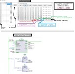
The Modbus Server I used, plus the TIA Modbus Client code:
00.jpg

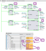
Code to swap the register words and re-assemble into 32-bit DWords (what Allen-Bradley can accomplish in two intelligent instructions it takes six overly-complicated Siemens instructions to do, because Europeans never shy away from unnecessary complexity)
02.png


A slightly different approach that takes only one more instruction:
01.png
 
First of all, thank you for the replies! This is beyond the help of what I ever imagined getting.


I should have mentioned that I am reading DINT since thats what the data format is in the manual.


Ive put my data length at 10 so I can see 5 addresses of DINT ahead.


So when I read 400001 it should should show 40000-1/3/5/7/9 right?


This is what it looks like when i read from address 400001:
attachment.php


attachment.php


And this is what it looks like when i read from address 400002:
attachment.php

attachment.php


The values on the physical screen are as follows(they are going up and down constantly though only slightly):
V L1-N 236,7
V L2-N 236,2
V L3-N 239,5


V L1-L2 409,1
V L2-L3 408,9
V L3-L1 409,3


This is what i get when read address 400063:
attachment.php
attachment.php


This is what i get when i read address 400064:
attachment.php


And this is the physical screen taken only few mins apart:
attachment.php


As you can see, if i take the value from TIA and divide by 10, i get a value thats fairly close.


So, should I still try and read it as Dword and try swapping around bytes see what I get, or it is something else thats doing this?

adr64.JPG current.jpg adr01.JPG adr02.JPG adr63.JPG
 
Certainly some byte swapping going on there. Looks like you want the first and fourth bytes, those add up to 273770031 which gets you to within 3.9kWh of the reading on the meter, assuming the last digit is a decimal.
 
If you change data format to hex it is easier to compare.


then copy hex value to internet calculator / converters and you can easier chech which bytes swaps.
Probably 3 and 1 bytes (LSB) are swapped and result is pretty near, but not exact result.
 
Code to swap the register words and re-assemble into 32-bit DWords (what Allen-Bradley can accomplish in two intelligent instructions it takes six overly-complicated Siemens instructions to do, because Europeans never shy away from unnecessary complexity)

A slightly different approach that takes only one more instruction:


Byte swap can done also whit "at slicing command" inside FC block. Another DB-memory area is still needed.
 
Byte [sic] swap can done also whit "at slicing command" inside FC block. Another DB-memory area is still needed.
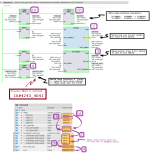
I apologize for my arrogance, and I stand corrected; only two instructions after all! Word slicing is an interesting contrast with A-B's BTD, and certainly close enough for government work.

Also ...

  • It is Word swapping that OP needs, not Byte swapping; the Byte swapping is effected in the Modbus drivers.
  • No need for a DB-memory area with slicing: the syntax references TheTag.%W1 and TheTag.%W0 can be used to write directly to the high and low words, respectively, of 32-bit integer TheTag; see below.
Untitled.png
 
@Drbitboy with SCL you have mulitple options of the swap function swap_word(), swap_dint() etc...

Not sure if they have the same instructions in LAD.
 
...
I should have mentioned that I am reading DINT since thats what the data format is in the manual.

Ive put my data length at 10 so I can see 5 addresses of DINT ahead.

So when I read 400001 it should should show 40000-1/3/5/7/9 right?

Yes, it shows all the bits of each pair ([400001,400002], [400003,400004[, etc.) but because the words are swapped, so the value interpreted from the bits is wrong.

As you can see, if i take the value from TIA and divide by 10, i get a value thats fairly close.

Like I said in the other post, you are being tricked (seduced) by values are that close to what you expect, because you are correcting the word swap by using the MSW (upper half) of one 32-bit integer (with the LSW (lower half) of an unrelated 32-bit integer.

Let me state this clearly:

  • ALL of the INT32s (32-bit integers) in the EM26-96 start on ODD values of MB_DATA_ADDR.
  • ANY value you derive from [EVEN-first,ODD-second] register pairs are meaningless.
So, should I still try and read it as Dword and try swapping around bytes see what I get, ...?

Swap the Words, not the Bytes (see Post #9), and read it as Words so make the swapping easier, but yes.

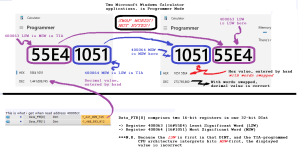
This image attached to this post demonstrates, that you retrieved the right 16-bit words from registers 400063 and 400064, but the order was reversed.
Untitled.png
 
First of all, thank you for the replies! This is beyond the help of what I ever imagined getting.


This is what it looks like when i read from address 400001:
attachment.php


attachment.php

attachment.php


The values on the physical screen are as follows(they are going up and down constantly though only slightly):
V L1-N 236,7
V L2-N 236,2
V L3-N 239,5


This is what i get when read address 400063:
attachment.php
attachment.php


And this is the physical screen taken only few mins apart:
attachment.php


As you can see, if i take the value from TIA and divide by 10, i get a value thats fairly close.


So, should I still try and read it as Dword and try swapping around bytes see what I get, or it is something else thats doing this?


You have value 1_441_009_745 on register 400063. If we take that to windows calculator (scientific selection) and change view to hex it is converted to 55E4 1051.
When we swap words it is 1051 55E4 and then back to decimals it means value 273 765 860.


Same for register 400001. There you have value 154_599_424 which is 937 0000 on hex.
Swapping words gives 937h which is 2359 (235,9V)
 
I apologize for my arrogance, and I stand corrected; only two instructions after all! Word slicing is an interesting contrast with A-B's BTD, and certainly close enough for government work.

Also ...

  • It is Word swapping that OP needs, not Byte swapping; the Byte swapping is effected in the Modbus drivers.
  • No need for a DB-memory area with slicing: the syntax references TheTag.%W1 and TheTag.%W0 can be used to write directly to the high and low words, respectively, of 32-bit integer TheTag; see below.


I meaned AT overlay variables on FC/FB blocks in and Out parameters.

Overall it is pretty same than .%W0 and %W1 and two move blocks are still needed for conversion inside FC block.


At is overlaying with different type and symbol name for original variable and %W is more like old hard coded adressing method.


https://support.industry.siemens.com/cs/af/en/view/57132240
 

Similar Topics

Hello, We're trying to connect to carlo gavazzi wm14-96 using tia portal. But we couldn't find any gsd file for it. Could you please help? Thanks
Replies
3
Views
1,129
Hello, i am using profibus as communication between plc and fanuc arm. I can easily send inputs from plc to arm, but i can't monitor any outputs...
Replies
0
Views
16
Hello, I need to write the following program in Ladder language, but I could not integrate the Fibonacci sequence into the ladder. Can you help...
Replies
11
Views
150
Hi All, Someone at work has put a PLC system on my desk, that's just been taken off an idle production line. He said "It's an S7 PLC. We don't...
Replies
10
Views
269
Back
Top Bottom