bit shift PLC instruction help please

unsaint33

Member
Join Date
Sep 2019
Location
MInnesota
Posts
114
Hi, I need some help write a PLC instruction. I am using Proficy Machine Edition 6.5.

Our indexing rotating table has 3 nests that are equally apart. #1 nest is for part sensing. #2 nest does nothing. #3 nest is for stamping.

If the part is detected, I want to activate the stamp. I want the shift to occur when the index motor is activated (Index_on). I want to assign 1 to a shifting register to indicate that the part is present (Part_present).

I am not familiar with any bit-shift instruction. if you could show a screenshot, that would be very helpful. Or just tell me what instruction I should use and what parameters should I use the Inex_on & Part_present.

Thank you.
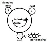
table.jpg
 
There should be a bit shift left (or Right) BSL BSR so you just set bit 0 (15) to a 1 or 0 then shift left or right.
Or as you only have a small number of shifts then on a one shot (pulse bit)
 
My question was not specific enough. got it. I read the manual and I still can not understand the technical explanations.

I see following parameters for bit shift word instruction; N, IN, B, OUT.

So, IN should be the word register, right? And N should be constant 1? Then, should I use Part_present as the B? Then, how do I make the index_on to trigger the shift?
 
I have never used proficy but have done a number of rotating tables with anything from 5 to 20 stations although the ones I did were far more complicated, just use a pulse off what ever the index trigger is i.e. when the table is told to index you put a 1 or zero in the start of the shift register (i.e. a part is present or not & when you get a pulse (note create the pulse one shot off the index signal as it has to be for only one scan). the number of indexes is obviously 1.
The ones I did had 3 shift registers one for part present, one for bad stamp (on any station) & one for part was not taken off at unload station (this one would go round 3 times if not removed on either the bad press or unload station then stop the machine.
although not proficy, see attached there is a simple way just using logic and a way using a bit shift function, the BSL function is probably different on yours but same idea on my system it is possible to address a bit in a word so for example a Word (16 bit) called Shift_word can be referenced as a word or as individual bits i.e. Shift_word.0, Shift_word.1 the dot suffix is the bit
 
What does the manual say?

Bit shift is a FIFO for bits, and has several "moving parts" (inputs and/or outputs):

  1. A trigger, the rising edge of which (usually) triggers a shift
  2. The source of the bit to shift INto the the bit-FIFO
  3. How many bits to shift per operation
  4. The length of the the bit-FIFO
  5. Bit storage for driving bit edge detection
  6. The (last?) bit shifted OUT of the bit-FIFO
  7. A word, or an array, to store the bits
Not all all bit shifts are implemented the same way e.g.

  • if the instruction does not allow bit storage for edge detection, then the programmer will have to manage edge detection separately.
  • there may not be an option to set the length of the bit-FIFO, it may only work on WORDs or DWORDS, which appears to be the case for Proficy. So in the OP's case, since there are only two bits in the FIFO, the code will have to look at bit 2 (assuming a left shift) to test whether there is a part at the stamping nest, where bit 2 was loaded as bit 0 two indexes previous.
  • the shift may do a wrap-around e.g. so a left shift may move bit 15 to bit 0; usually this is a different instruction e.g. ROL_WORD or ROR_WORD.
From glancing at this video, it looks like, for OP's case using the SHIFTL_WORD instruction,

  • ENABLE ("power flow") will be a one-scan pulse (trigger) from the rising edge of the index_on bit
    • N.B. this will not be index_on itself
  • IN will be the WORD has its bits shifted; the only bits of interest will be bit 0, bit 1, and bit 2.
    • That same WORD will also be assigned to output Q, to receive the shifted state after the shift.
  • The N input value will be 1 - the number of bits to shift per index trigger
  • The B1 discrete input is the state of the "Part present" from nest 1 at the time of the rising edge, i.e. the source bit to push onto the bit-FIFO
  • The B2 discrete output will be ignored; it will pop out of the FIFO at the 16th index trigger and be long obsolete by then
  • The bit that indicates whether a part is present at the stamping nest will be bit 2 of the WORD used as the IN input and the Q output.
Although, since it's only a few nests, this might also work

Code:
    index_on     index_M  index_ons
------] [-----+----]/[-------( )-----+--
              |                      |
              |  index_M             |
              +----( )---------------+


     stamp2  index_ons    stamp2
--+---] [-------]/[----+---( )----
  |                    |
  |  fifo1   index_ons |
  +---] [-------] [----+


     fifo1   index_ons    fifo1
--+---] [-------]/[----+---( )----
  |                    |
  |  fifo0   index_ons |
  +---] [-------] [----+


     fifo0   index_ons    fifo0
--+---] [-------]/[----+---( )----
  |                    |
  |  nest1   index_ons |
  +---] [-------] [----+
 
There are four inputs and three outputs for the SHIFTL_WORD instruction.

The top input is boolean logic flow and is the enabling logic. When true, the shift is performed. Unless you want the shift to be performed every scan, make sure this input is a one-shot.

The input labeled "IN" is the address of the starting point of the range of bits to be shifted. If you leave the value inside the function at its default setting of 1, the range of the shift is 16 bits starting at the address specified at "IN". A value of 2 inside the box sets a range of 32 bits, etc.

The input labeled "N" wants numeric data. It is the number of places to shift each time the enabling logic is true. Most of the time this value is 1.

The input B1 is boolean. When true, you shift a "1" into the bit array. When false, you shift in a "0".

The "Q" output is the starting address of the shifted bits. In the OP's case it should be the same address as the "IN" input.

The B2 output is optional and boolean. It is true if the bit shifted out is true. It won't be of any use in the OP's case since he's only interested in the value two positions downstream.

If the OP uses a SHIFTL_WORD instruction with a length of 1 and address %M0017, then %M0019 will represent the presense or absense of a part at the stamping nest. Note that the starting address needs to be on a byte boundary, %M0001, %M0009, %M0017, %M0025 etc.
 
Code:
    index_on     index_M  index_ons
------] [-----+----]/[-------( )-----+--
              |                      |
              |  index_M             |
              +----( )---------------+

   index_ons
------] [-----+----[ADD  ]-------+---
              |    [ibits]       |
              |    [ibits]       |
              |    [ibits]       |
              |                  |
              |  nest1  ibits.0  |
              +---] [-----(S)----+

                ibits.2  stamp3
--------------+---] [-----( )----+----
              |                  |
              |         ibits.3  |
              +-----------(R)----+
The last branch protects against overflow in the MULtiply, and may not be necessary.
 
may i suggest this.
you have the following bits, bit1, bit2, bit3, and bit4
place the part onto the table.
when you trigger the system to index,
move bit3 to bit4
move bit2 to bit3
move bit1 to bit2
move 0 into bit1
move 1 into bit1 if there is a part
increment the part.
cheap way of doing a bit shift.
bit 4 is for when someone asks what was the processed last time.
james
 
Code:
    index_on     index_M  index_ons
------] [-----+----]/[-------( )-----+--
              |                      |
              |  index_M             |
              +----( )---------------+

   index_ons
------] [-----+----[ADD  ]-------+---
              |    [ibits]       |
              |    [ibits]       |
              |    [ibits]       |
              |                  |
              |  nest1  ibits.0  |
              +---] [-----(S)----+

                ibits.2  stamp3
--------------+---] [-----( )----+----
              |                  |
              |         ibits.3  |
              +-----------(R)----+
The last branch protects against overflow in the MULtiply, and may not be necessary.

I do not follow the first rung. index_M must be the motor contactor feedback? If so, index_M will turn on (on the 2nd line) then index_ons will will turn off on the next scan, right?
 
I do not follow the first rung. index_M must be the motor contactor feedback? If so, index_M will turn on (on the 2nd line) then index_ons will will turn off on the next scan, right?

Summary

Not sure what you mean, and yes.

The first rung is an explicit* algorithm implementing logic for a one-shot a.k.a rising edge detector a.k.a. pulse.

Details


The first output bit index_ons** will be true, for one scan only, when a rising edge, i.e. a transition from 0 to 1, is detected in OP's index motor bit (index_on) from the previous scan. The second output bit index_M*** represents the storage bit necessary to implement one-shot logic; in some OEMs one-shot instructions it is built-in to the instruction, in others the programmer must create a tag and supply it.

* I was too lazy to look up the Proficy manual to see its symbol in this thread's context ;).

** _ons => ONe-Shot

*** _M => Memory i.e. state of index_on from the previous scan
 
Last edited:
Summary

Not sure what you mean, and yes.

The first rung is an explicit* algorithm implementing logic for a one-shot a.k.a rising edge detector a.k.a. pulse.

Details


The first output bit index_ons** will be true, for one scan only, when a rising edge, i.e. a transition from 0 to 1, is detected in OP's index motor bit (index_on) from the previous scan. The second output bit index_M*** represents the storage bit necessary to implement one-shot logic; in some OEMs one-shot instructions it is built-in to the instruction, in others the programmer must create a tag and supply it.

* I was too lazy to look up the Proficy manual to see its symbol in this thread's context ;).

** _ons => ONe-Shot

*** _M => Memory i.e. state of index_on from the previous scan
Makes perfect sense. Thank you so much.
 

Similar Topics

Hi All. I have a very specific question about tracking using an encoder and bitshift register. We would like to use a Compact or Control Logix PLC...
Replies
40
Views
1,687
Hello. I've been using the answers in this forum for a while now, so thank you. Usually I can find the answer I'm looking for with a basic...
Replies
8
Views
741
Good morning (EST), I am trying to implement the code below in on an S7-1200. It's barely half a dozen instructions, but I am stuck; I have not...
Replies
26
Views
5,636
I have a program I need to work out for a client and I'm having trouble figuring out the correct logic to do it. Let me see if I can explain it...
Replies
27
Views
6,439
I am having trouble figuring out how to track a product using a BSL instruction. The way that I have it set up is: I have an infeed eye that...
Replies
10
Views
2,732
Back
Top Bottom