Omron vs simatic Toggle button???

Jirrr

Member
Join Date
Jan 2009
Location
Czech
Posts
167
Hello,

maybe someone can give me an advice....

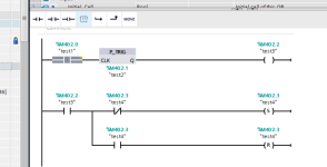
Why in omron PLC /cx-programmer/ ladder program in attachement works like an one button toggle function....and in tia portal the same program does not work????....in tia portal/s7-1200/ keep function is alternated by set/reset coils....

Thanks a lot....

omron toggle.PNG
 
....I know that my program in simatic can not work /see atch./....and I know how to program toggle button in simatic.....what I do not know why Keep works like this in Omron Plc....It should not work!!!!...I remember that some plc types evaluate program in rung not in lines but in culumns,but I do not know how it is in Omron????

thanks...

simaticToggle.PNG
 
It's probably that the keep function differs from the set/reset function.
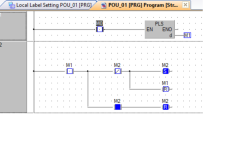
If you transpose the set/reset on the second ladder the latch will latch but never unlatch, I suspect that the keep function works by using non dispay internal bits that act as ones hots but these are reset internally in the function this would be like to set the latch it also resets the pulse bit.
see pic
although just adding a reset of the pulse to the set rung works so I bet like counters although the count contact stays on it only counts on rising edge so it seems Omron have built in one shots on their Keep function.
In the pic normally the one shot M1 will be on for 1 scan so as M1 is pulsed it sets M2 as the ladder is scanned left to right top to bottom it then resets it strait away, the Omron uses edge trigger in the Keep function so I assume it's internal edge trigger is reset by itself before evaluating the reset operation

Mod Pls.png
 
Last edited:
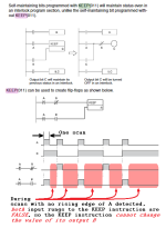
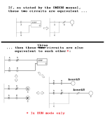
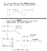
Why do you think it not should work? The manual states that a circuit, which is equivalent to OP's example circuit from Post #1 in this thread, should work as a flip-flop (see image adapted from Omron manual below).

N.B. on the single scan when

  • EITHER
    • the rising edge of A is detected in the image below, which sets the output rungs of the -]^[- instructions to true,
  • OR
    • the rising edge a 380.00 is detected in Post #1, which (eventually) sets the output rung of the NC(381.00) instruction to true in Post #1,
then one of the two input rungs of the KEEP must be true, which will in turn toggle (flip-flop) the output bit.

On any other scan, when no rising edge is detected because

  • EITHER
    • A/380.00 is 0,
  • OR
    • A/380.00 was 1 in on the previous scan,
then all inputs to the Set-Reset/KEEP instructions will be 0, and the output will not change.

How is that behavior anything other than what the KEEP instruction is designed to do?

xxx.png...yyy.png
 
Last edited:
to Parky.....if You reset M1/like on Your atach/ it will work.....probably KEEP f.
has this functionality implemented...

to Drbitboy.....I must study documentation better....I presumed that KEEP function is equivalent SET/RESET function in Tia portal....

thanks....
 
...I presumed that KEEP function is equivalent SET/RESET function in Tia portal....
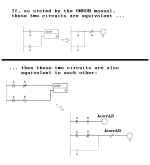
KEEP is equivalent, but to a [SET+RESET] instruction pair; see the image below.

The key to understanding why that flip-flop logic works with KEEP is that for scans where both KEEP inputs are False, the KEEP does nothing. the pulse instructions as shown ensure that indeed both KEEP inputs are both False for scans after the initial scan that detects a rising edge until the next rising edge.

yyy.png
 
Last edited:
...hhhh....how can be KEEP and set/reset pair equivalent.....on the picture there is A,B vars with KEEP and A,B,C vars with set/reset.....???....set/reset from the picture can not work at all....
 
by the way...I tested 3rd connection also....it cant work as well....only KEEP function on the picture works....
 
I cannot test Omron, and it's been many years since I last did one, I do remember a similar problem I had, I deduced that the Keep function (although the equivelent to the SR function does use edge triggering, as only Omron know how the compiled code works we can only guess.
Many PLC's do not actually compile the ladder code directly into machine code (this is due to the legacy of early PLC's not having structured blocks, i.e. the program was effectively one long block of code, This becomes a problem for on-line changes, compiling the complete ladder & downloading it will cause major delays so many had different ways to do it, I know many actually had an interpreter so the plc ladder was not exactly compiled but much like basic, it generated operation codes, these called compiled functions if you like.
Siemens S5 was a typical example, S5 used what they called MC5 (I suppose it was short for machine code 5), for example an instruction like AND I0.3 was converted into a 16 bit MC5 hex value, cannot off hand remember them but let's assume the Hex code was C05E, part of it was the AND & the other was the address, the interpreter would then call the machine code the processor understood, you must remember that like basic, it interprets the basic into a block of machine instructions I suppose you could call it a lookup table, this called the compiled instruction.
So it is probable that when Omron designed their PLC, the Keep instruction (call it a function block or AOI but in Machine code) would be a jump to a function that did the actual work.
so for example:
What would seem a simple instruction would contain probably many instructions I do not know the actual instructions but ....
if it was in plain language the keep function might be
load Set bit
Pulse a temp
AND the temp
Set The keep
Reset the temp
Load Reset Bit
Pulse a temp
Reset The Keep
Reset the Temp
Whereas, the normal Set/Reset in other PLC's may not have the reset of the pulse ones hot.

Siemens were way ahead of most PLC's, their system was structured into blocks, the ram that held the program was sort of formatted like a hard disk so it contained a type of File Allocation Table, when you downloaded a a program block (PB,FB,DB,OB) the original if it existed was not overitten but was loaded into spare ram, at the PLC housekeeping (at the end of program scan or before) the FAT table was updated with the address of the new block, the original block was not deleted just like your PC, your hard disk contains many old files, these are then written over as new files are saved to the HD, Originally Siemens did not automatically overwrite the old data & you had to compress the ram with the Programming console when there was no spare room, later this was done automatically, this was the reason that on Siemens you could download the whole program while in run mode, most even now you cannot (before some bright spark says that can cause problems yes, but if those blocks are downloaded in order i.e. PB,FB,DB, OB then it is safe).
I know that Mitsubishi is limited to about a max of 500 byte on-line change, effectively the PLC code is one long bit of code, the main routine has what they call an FEND this is the end of the main routine (Scan), jumps or calls to other blocks like functions jump to labels past the FEND instruction run the routine then return, when an on-line change is done I do believe parts of the code may be padded out with NOP's when changed code is downloaded this allows small changes without having to shift the program too much that may cause extra long scan time.
I do not pretend to know exactly how all of the above is achieved, some I'm sure about & some is assumed on what I have learnt working with a couple of engineers who have designed their own systems, who most certainly had some inside information.
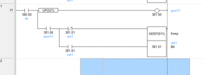
 
....You are right....I simply presume that inside KEEP function there is part of program which prevent SET and RESET in the same cycle which can be programmed in many ways.....

...main point of my problem was that when I saw program in omron plc I said maitenance boys that it can not work like this/I thought in siemens way/.....in the end problem was in different part of program....but it is good to know how KEEP function works...

thanks a lot.....
 
Well, It is assumed that this is the way it works one of the things people do not realise is that many PLC programs are not compiled directly into machine code (this makes them more flexible take an example of a shift register.
If you create your own) for example
for x = 0 to 200
etc.....
next
(Note: it depends on the PLC some do not use for but just use jump back until x = 200) but I'm sure you understand.
Now that loop takes time as each instruction is interpreted (or compiled line by line), however, if you use a built in function for a shift then it probably does the same loop but as it is machine code i.e. it is just a call to an already compiled function then it is faster as it does not need to evaluate it as such so is a lot faster, I have tried this on many PLC's, there has been a number of posts here regarding shift registers & it nearly always turns out that using the in-built function is many times faster. I suppose the IDE compiler (if that is what is used) could build the machine code into the actual running code & possibly some do and in theory would be just as fast but that is not my experience.
 
Whoops, there was a typo and another mistake in the previous image:

  • C should have been B;
  • Also, needed to prevent prevent Reset in Set+Reset example from executing when A has rising edge and B was originally 0 so Set executed;
  • Both errors are fixed below.
The approaches on the lower-left and lower-right should work on any PLC; by inspection I think we can all agree that each of those two does execute a flip-flop.

The approach on the lower-left is most like the KEEP, according to the description of KEEP in the Omron document.


xxx.png
 
to Drbitboy....I do not test it but now all examples should work without problems....

to Parky.....I agree....


Thanks....
 

Similar Topics

hello eb i have an omron PANAL and i want connect it with a s7-300 plc , i want know the way of communication can i make it for that hardwares ...
Replies
4
Views
2,659
Hi dear . I have a system with cj1m cpu11 etn. previously NT 5z HMI was connected with plc. recently my old HMI got damaged. I want to replace it...
Replies
5
Views
29
Omron AD081-V1 Analog Input Card Offset & Gain Adjustment Entering Adjustment Mode 1. Set the input card in adjustment mode (Turn ON Dip SW No-1)...
Replies
0
Views
24
I am working on a project using a NB screen and NX1P2 PLC. I am having a really hard time getting a real number to properly translate through to...
Replies
3
Views
104
Hi, I am facing an error inside Omron Network Configurator. I have 2 PLC communicate each other using ethernet cable, send signal using Network...
Replies
2
Views
90
Back
Top Bottom