Yaskawa Modbus

smiley125

Member
Join Date
Apr 2014
Location
UK
Posts
9
HI

I am setting out on my first (cross brand) Modbus journey and looking for some help.

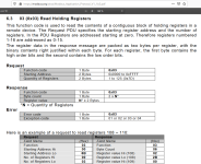
I have a Yaskawa Ga700 Drive fitted with their SI-EM3D Modbus TCP card, Initially I am trying to read from their addresses (hex) 2000 - 2008 (I'll attach a segment of the manual that show this).

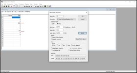
I am Trying to read them using Modbus Poll. If I address from 2000 with 16 rows I can see 2004-2008 but nothing before that, I assume I am addressing something wrong if I can see some of the functions but not others all offset by 1 address. (Proving that I have communication)

I hope this makes enough sense, thanks for any help.
modbus poll.jpg yaskawa si-em3d.jpg
 
Hi Smiley!


Modbus addresses start at 1, but on the wire you send 'address - 1'.


You can see in the modbus pool screenshot that 0x2000 is actually an odd PLC address (48193). This is because it is actually referring to address 0x2001.


I suspect the other registers are supposed to be zero. (no torque reference, zero actual speed, nothing wired to terminal A2, etc.)
 
No matter how specific and clear you try to be, multi-vendor Modbus addressing has a very high risk of confusion, especially when there is translation between human languages involved.

I disagree (respectfully !) with Ian; you can see in the actual RTU poll bytes in the Modbus Poll that it's really polling address 0x2000.

01 03 20 00 00 0A CE 0D

The Modbus Poll utility screenshot is only polling ten registers, not sixteen. The Modbus Poll utility sets the "address mode" for hexadecimal but only the "Address" field is affected.

The address space that's being read is special high-speed access memory in the Modbus TCP adapter module: there are just seventeen registers of the drive in that area.

The paragraph that appears above the table in the Yaskawa manual (seen in the second screenshot) describes that data memory as "Modus TCP/IP registers 01H to 01FH".

But wait: there are seventeen registers in that data space, addressed 0x2000 to 0x2010. That's not 01H to 01FH, which is thirty-one registers and begins at 1, not 0.

So..... try starting with address 0x2001, and reading 16 or 17 elements at a time, and try to correlate one of the drive registers with one of the Modbus registers to be sure you're lining them up right.
 
Last edited:
Perhaps my favourite thing about modbus is that the spec is available for free online:
https://modbus.org/docs/Modbus_Application_Protocol_V1_1b3.pdf


Not even my least favourite thing is that there are two 'addresses', one starting at zero, another starting at one.


In the spec, you can see them sending address 0x006B (107 in decimal) to access modbus register 108. Even for devices from the same vendor, I go into a modbus integration expecting a 50% chance of increasing or decreasing the address request.

Ken, my assumption that the address 2000 typed in modbus poll is indeed different to the address 2000 in the yaskawa manual, is because 5000 sounds like a reasonable speed reference for 50cHz, and 329 sounds like a reasonable DC Bus voltage for 240V 1~. They appear in the screenshot at the 2000+3 register and 2000+7 register, but the Yaskawa Manual has then as 2004 and 2008.


yaskawa manual


Reading the same paragraph, "All of the drive command registers have been mapped to this high speed access area (Modbus TCP/IP registers 01H to 01FH). In addition, the monitors shown in Table 9 are mapped for high speed access," I get that the command registers for setting the speed and starting and stopping are at 0x0001 to 0x001F. The feedback of actual values can be read from 0x2000 to 0x2010. (or 0x1999 to 0x200F "on the wire")

It seems to say you need to look at the Ga700 manual itself, to know which command registers it puts in 0x0001 to 0x001F.


Ken is right that you will need to set the quantity in decimal for modbuspoll.

2021_07_26_22_04_55_Window.png
 
Last edited:
Oh, that's excellent. Ian's correlation based on reasonable values for Hz and Bus Voltage is almost certainly correct.

So change the polling address to 0x1999, and all the correct data should show up in the registers you expect.
 

Similar Topics

Hi, I have several Yaskawa V1000 VFDs connected via Serial Modbus to Opto22 serial modules. Everything is sort of working. I was able to set...
Replies
3
Views
1,941
I'm getting ready to do a lab on communicating directly from an Automation Direct HMI to a Yaskawa V1000 using Modbus RTU. Surprisingly, I've...
Replies
4
Views
3,066
Hi guys. I have a some-what noobish question. I have been doing light plc programing for the last year or so, mostly with descreate I/O's, simple...
Replies
6
Views
3,841
I finally get to play around with connecting a PLC to a Drive via Modbus TCP. The frustrating part of the process is finding good tutorials or...
Replies
3
Views
3,291
I'm creating a new HMI to communicate with a Yaskawa controller. I started adding some of the values to the screen from the 4XXXXX registers and...
Replies
2
Views
2,436
Back
Top Bottom