Trying to test FTVS with PLC attached to laptop, not working

JZerb

Member
Join Date
Oct 2016
Location
Here
Posts
421
so im trying to test something with a PLC attached to my laptop thats mounted on a board with some lights and switches, but im having no luck and im hoping to be pointed in the right direction.

what ive done.
Opened RSlinx classic, connected to the PLC

Opened RSLogix500 and downloaded the ladder into the PLC

Closed RSLinx

Opened FTVS, went to RSLinx Enterprise-->Communication Setup
-Device shortcuts, Add, used name ML1200
-Design (Local) tab, right clicked on the RSLinx Enterprise at the top, add driver. added a Serial-DF1 driver. The Micrologix 1200 shows up in the tree. I click on that to highlight it, click on the ML1200 name over to the left in the Device Shortcuts list hit Apply, and all is well.

In FTVS i open up the HMI Tags menu, Create a folder named PLC, go to the DB Browser, use the RSLinx name of the device ML1200 to import tags into the PLC folder and then close the Tags window.\

Go to Displays, open up the MAIN display and proceed to put a Maintained Push Button on it. go into that push buttons properties and in the Value level click on Tag, the Tag Browser pops up and i navigate my way to the PLC folder from the previous step and see all of my tags that were imported from the .RSS file. i then tie the Push Button to an input tag on the PLC that when good will turn a light on.

Go to Test Display, and no dice. The light does no turn on. I could have sworn ive gotten this to work before, but watching the same videos that made me successful the first time havent gotten me there this time so hopefully someone can shed some light on what im doing wrong here.
 
Its been a long time since I used FTVS....

But it sounds like you are trying to use your PC to test the project and not download the application to a PV....correct?

I cant remember for sure but I think you still need to create a runtime for it to work on the pc as well.

Once you get your button and everything you want put in place, click on the running man icon on your tool bar and create a runtime....then try to test your application.

I could be mistaken about this since it has been some time since I have used FTVS, but give it a shot and see where you get with that.

If I am wrong someone will be by shortly to get you on the right track.👨🏻‍🏫

BCS

I thought that as well and tried it. Still no luck. You are correct though. I'm trying to test the project on a PC due to lack of a Panelview.

I did copy the Design comm setup to the Runtime tab as well yes. Forgot to mention that in first post
 
That I'll have to double check. I did hit verify, then ok. but I may have hit it while I was in the Design tab if that matters.
 
bumping this up for the Monday morning crowd. i double checked this am when i came into work that i did copy the settings over from the Design to the Runtime tab, hit Verify and then OK to close the Communication Setup window.
 
Instead of using Test Display use the Running Man. The Test Display does not have give you full functional capability.
 
i have tried both Test Display and the Running Man (test application) and have had the same results for both. i will post up some screenshots of what im dealing with and perhaps that will help. im sure im missing something stupid because i HAVE done this before.
 
Just one question. Does your program contain a subroutine. if so, are you calling that subroutine? We have all made that mistake.o_O
 
Let's first verify that you have communications. It could very well be that it is the subroutine issue in your logic. But let's make sure that View is seeing your PLC.

The easiest way is to go back to your pushbutton object and try to select a tag directly from the PLC. Not the HMI tag you imported.

Using the tag browser expand the ML1200 shortcut and select Online. See if any of the tags (data files) appear you should be able to see the data files in this list.

If you cannot expand to see Online or what is underneath, then you have a communications issue with your driver or your shortcut.

On the Communications window you must click OK for any changes to kick in. The Verify is not needed. It is for you only. The program doesn't care if you Verify or not. And for now just stick with testing the display. The Running Man - Test Application is overkill at this point.

FYI the running man option uses the Design communications setting. The Runtime tab is only for saving those settings as part of the runtime file.

OG
 
Last edited:
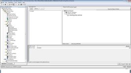
RSLinx Communications Screen, then screenshots of the two buttons i have setup on the screen.

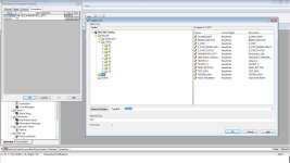
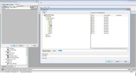
one button i have setup for the HMI tag address that i brought into FTVS via the DB Browser and the HMI tag editor window. the other button i have setup as you specified above. neither of which work still. i do have a JSR command in my logic, i went back and double checked that as well.

PVP_Test.jpg PVP_Test_1.jpg PVP_Test_2.jpg
 
The bit identifier within a word of the RSLogix 500 SLC/MicroLogix platform uses "/" rather than "."

Make you Online browsed Connection {::[ML1200]I0:0/1} for Bit 1 of the Word 0 of file I0.
 
Last edited:
You've probably got everything right. Your HMI (or at least, your PC pretending to be a HMI) is probably sending a message to the PLC to say "turn on I:0/1", and your PLC is doing exactly as it is asked.

Then, about 0.01seconds later, your PLC is reading the status of I:0/1 from the actual onboard input terminal, finding that it's off, and updating the register in the PLC to indicate as such.

tl;dr, never, ever address physical I/O directly from a HMI. Use N or B registers, and map from there in the PLC code.
 
Wait - just re-read and realised you're not trying to write to your input, you're trying to read it to change the indication on your pushbutton. So, more likely your issue is what dmargineau noted above my post.

That said, I still stand by my tl;dr - directly addressing I/O registers from a HMI is just asking for trouble. I've tried it once or twice and never had it work neatly or reliably. Map it to an N register - you can COP the whole input word and have it done in one rung.
 

Similar Topics

Hey guys, I've got a system I'm coded up, it is using three SCADAPack 357 controllers. Out in the field, they'll communicate via TeleDesign...
Replies
5
Views
2,335
I can't seem to get the Panel View Plus 7 standard edition to downgrade to V_11, when I check the AB downloads and compatibility websites for this...
Replies
1
Views
123
Hi I used to be able to launch PLCsim without any problem. Now it tells me " STEP 7 Professional Licence is required to simulate this PLC"...
Replies
15
Views
511
Hello! When trying to load the hardware configuration I get error 0050-133 2 2458, check the diagnostic buffer. When checking the buffer, it says...
Replies
4
Views
180
Back
Top Bottom