Set in RSLogix 5000 pid

frank222

Member
Join Date
Dec 2010
Location
holanda
Posts
12
Hi all
how could configure a pid in RSLogix 5000, if anyone has an example or project done, even completely fail to understand the operation and configuration in RSLogix 5000 and driving me crazy, thanks in advance for your help
 
we'll plug an example PID into your program for you if you'll post your existing ACD file (you'll have to zip it first - forum rule) ...

tell us which of your existing analog input and output signals you want to use ... tell us how those signals are scaled (example: 4 to 20 milliamps equals 0 to 200 degrees, etc.) ...

the more you tell us about your system, the more detail we can provide ... if you're just using a "make believe" system to play with that's OK too ... just tell us so - and make it as realistic as possible ...
 
I send in RSLogix5000 settings, the process is as follows: it is to control the load of a mill, a feed mill product dispensed is controlled by a variable speed drive, the feeder dosed according to the mill motor load (amps), my analog input is the mill motor load and my 4-20ma analog output is 4-20mA control the feeder speed, I'm using a CompactLogix with analog input module 1769-IF4 and 1769 analog output module OF4CI, my question is how to configure the modules and how should climb, and set the pid, the rated load of the mill motor is 150A, thanks for your help and guidance
Deshacer cambios
 
the file in your zip attachment has an RAR extension ... we need the file with the ACD extension ...

note that if the ACD file is too large to send (even zipped) then use RSLogix5000 to do a "File - Save As" operation and save the file as an L5K type file ... this will be much smaller .. then zip that L5K file and attach it here ...

 
In RS5000, do you have an editor option? Otherwise, you won't be able to edit the PID. Found out the hard way.

George
 
here's the best that I can do based on what you've posted – and within the limited time that I have available ...

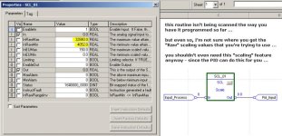
(1) first of all, the SCL (Scaling) operation that you have in the Function Block Routine wouldn't work the way that you have it programmed – simply because the routine isn't being scanned ... (a JSR instruction in the Main Routine would be the customary way of taking care of this issue) ...

(2) and where did you get the values (4052 and 32840) that you're using in the SCL? ...

(3) based on the information that I have available, the values 6241 and 31206 would be correct ... see page 3-11 in the following manual ... I've also included a screen shot below to highlight the information that I think you need ...

http://literature.rockwellautomation.com/idc/groups/literature/documents/um/1769-um002_-en-p.pdf

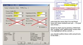
(4) going further, you probably don’t need the SCL at all – since the PID instruction itself can perform the scaling that you need ... see the screen shot below for how this is normally set up on the PID's Scaling tab ...

(5) you have the PID on an unconditional rung in the Main Routine of the Continuous Task ... that means that the PID would execute on each and every scan ... this would make your Integral and Derivative actions EXTREMELY difficult (if not impossible) to tune ...

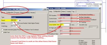
(6) I've moved the PID into a Periodic Task – with a period setting of 500 milliseconds ... this should make the PID execute only once each half-second ... note in the screen shot how the Period of the task has been set up to match the PID's Loop Update Time setting ...

(7) the 500 millisecond settings I've used were chosen as EXAMPLES ... in your application, you might need to increase the speed of the task update – but if you do, you should also change the PID's Loop Update Time setting to match ...

(8) note that I've red-lined a lot of the information on the screen shots – to indicate that I have NOT had time to look at these settings ... I'm out of time – but I hope that this information will at least get you closer to where you need to be ...

(9) DISCLAIMER: I've done the best I can with the information and the time I have available ... you're there with the project – and I'm not – so take everything that I've said with the proverbial grain of salt ...

good luck with your project ...

.

pid_timing.jpg pid_scaling.jpg scl_function.jpg
 

Attachments

  • Mill_Roller_Ron.zip
    235.6 KB · Views: 257
  • Mill_Roller_Ron.pdf
    11 KB · Views: 394
Thanks for your help Ron
But still I have some doubts, please, I am not clear even control configuration variable (CV) and configure the maximum output at 100% and Tieback.
Ron, the PID will be running in the periodic task, but when I start the engine of the drive should start dosing 0Hz, reaching the desired speed according to SP main engine load when the engine shuts down the PID dispenser not should be executed, or continue to run, or be placed 0 to SP, that part of the structure of the PID would use to stop and start the PID or how it should be set.

thanks


Deshacer cambios

Alpha


Ejemplo del uso de "":


traducido automáticamente por Google


sustantivo


thanks
gracias
 

Similar Topics

Processor: 1769-L30ER; Logix 5000: v32.02 I have an AOI that's been used in previous applications without issue, and have added a TON...
Replies
6
Views
2,746
I have a question on a subject of etherent nodes in rslogix 5000 project tree for a project that I am working on. I am trying to read if read...
Replies
5
Views
4,672
for some reason when i try to change the value for the preset on a rto timer after i change it accept changes it goes back to the old value, any...
Replies
4
Views
2,183
Hello Everybody.. I am attempting to get online with our PLC via the Ethernet/IP card that is tied into our Wonderware 14 port managed switch...
Replies
37
Views
17,219
To All, Please help, I am new to Rockwell automation and normally use Siemens, I am trying to finish up a program and now need to use a "Heart...
Replies
9
Views
18,097
Back
Top Bottom