ASCii Line Feed Data

PLChristian

Member
Join Date
May 2021
Location
Wisconsin
Posts
27
Hello all, as you probably are all aware I have been trying to interface an A&D GX4002A balance to a 1769-L24ER-QBFC1B controller by the use of a 1769-ASCII card. I am wondering if there is a way I can cycle each string in one at a time so there is no potential for corrupted data when the registers are updating. As of now I have the start and stop delimiters set which gives me the ascii string, but when the value from the balance changes the registers start changing in that same string so I am worried that when the ascii card is scanning at a fast pace the register might be caught between an update and give me bad data. Is there possibly a way where I can have the complete strings cycle through one at a time instead of just updating the registers in one particular string?
 
I don't understand. Is the 1769-ASCII card continually updating the string in the -L24ER, and you are parsing the string across several scans? If yes, then you could buffer the string to another string, e.g. on the rising edge of the done/complete bit, to another location, and then disable that buffering until the buffered copy is parsed.
 
I don't have hands-on experience with the 1769-ASCII card, but all the BASIC modules I have used included the ability to query the serial port buffer to find out how many characters it contained. Assuming that the balance is spitting out character strings as fast as it can, could you check for the number of characters in the serial port buffer. When the character count exceeds the size of a single measurement, fetch only the characters up to the delimiter (CR/LF ??). Then extract the weight data from the string.

You will need to flush the serial port buffer each time you have to restart the program in the 1769-ASCII module. And if the balance can spit out new measurements faster than the ASCII module can process requests for the character count in the buffer you'll need a different strategy.
 
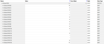
So I have both the start and stop delimiters set and with these set only these 17 registers can update. My worry is that when I'm scanning at 20 ms one of these registers may be caught in the middle of an update and give me a false value.

Capture2.PNG
 
The ARL command transfers data by reading from the device buffer and writing to the SINT array (registers; string). The logic can control when that transfer occurs, so it can also prevent it from happening e.g. when the .DN or .EM bit is 1 and the string is not yet parsed.

What does the logic look like now? Is the .FD bit from an ABL instruction controlling the ARL? What logic sets the state of the EnableIn rung of the ABL instruction? Is some or all of this happening in the main routine or in interrupt routines?

Both ABL and ARL instructions are transitional i.e. they are enabled by the rising edge of the input rung, so the logic has to toggle the rung back to false and then to true to read the data again.

The parsing can be triggered by the ARL .EM bit and should, I expect, complete in that same single scan, but even if it does not, as long as that parsing prevents the ARL from running again, the array will not be overwritten.
 
Take a step back, folks: This is a 1769-ASCII module, not a controller serial port using ASCII instructions. The complexities of the Channel 0 buffer and the ARL/ARD instructions are not relevant.

The 1769-ASCII module accepts a string of data until it encounters a fixed buffer length or delimiter characters. It then populates an Input tag all at once with the status counters, the length of the data, and the data itself.

OP's logic very probably copies the InputTag:RxDataLength (an INT) and the InputTag:RxData[x] (a SINT array) to the .LEN and .DATA elements of a String tag before executing the String to REAL conversion.

To remove any concerns about asynchronous data handling, use the Copy Synchronous (CPS) instruction to copy the Input data elements to the String elements just once when the InputData:Ch0RxID value increments.
 
Thanks for the help guys, I followed the example provided and used the trend feature under assets to view the scans live and everything looks good.
 

Similar Topics

I am using an AB1769-ASCII card and a 1796-L24ER controller to read data from a scale. The data I am currently receiving is all Line Feed data...
Replies
7
Views
2,543
Hi, I need to send a command from a S7-300 with a CP341 in ASCII format (RS485). I can get the command to send fine, what I need to do is add...
Replies
1
Views
6,237
Hi all, I'm trying to use the "Test ASCII Buffer for Line" Instruction in a AB SLC500, and are having some trouble. What I am having trouble...
Replies
5
Views
5,543
Hi, We couldn’t find anything specific, so am starting a new thread. I’m trying to migrate a config from a ML1400 to a micro820 & am experiencing...
Replies
1
Views
68
I have an L24ER-QB1B with a 1769-ASCII card in slot number 4. I'm looking to send data to this zebra printer after every completed sequence. I'm a...
Replies
2
Views
425
Back
Top Bottom