In over my head (ladder logic) Horner PLC, serial Barcode scan

And your point is?, It is exactly as I said, either use the terminator char, or checksum or length, it's simple, no need to complicate it, if the data comes in the wrong order then there is a serious problem how that can happen is beyond me the data is serial, how a uart can mix them up is also beyond me, the only reason I can see that happening is the code that controls putting the data into the user variables which is part of the operating system, wrong chars yes, but for a robust system use checksum, not perfect but pretty reliable. A system I put in a major supply part of a multi national company had 8 scanners on the system, this was in 1992, the readers in ASCII mode did not support checksum, it was simple node number, control chars, data, cr. the process of getting the codes was as simple as I have already posted.
The company I worked for went into liquidation in 2001, a colleague I worked with who was also on the project took over any future work with the customer & continues that today, there have been no reports of corrupted data, approximately 10 mis-reads a 8 hour shift, and this is almost exclusively a no read due to barcode not fitted or lost, damaged bar code.
(just to put you in the picture the bar codes are not stuck to the totes, there is a pocket for them to be fitted into well actually slots, these are simple thin cards, are are not secured so on return of the tote, these are de-stacked, turned upside down to remove debris & the bar code).
I have only a rough idea of the throughput, but as at very least each tote is read 3 times, some 8 times before reaching the final stackers, This then means at the very minimum over 43,000 reads per shift.
 
And your point is?, It is exactly as I said, either use the terminator char, ...

My point is indeed exactly that, as I said well before anyone else i.e. in the first reply in the thread in Post #2; see here.

The issue that follows from that main point is understanding how the RECV instruction works to be able to test for a carriage return; the video should resolve this issue.

From the video, it looks like the RECV rung does not need a one-shot memory bit; it can be done with just the one Read_Complete bit i.e.

Read_Complete Read_Complete
-------]/[----------[RECV ...]-------( )--------


The RECV instruction will not complete until all bytes have been read, e.g. so a short barcode of 27 characters or less, with the [Bytes] input parameter set to 29 (28 chars + carriage return) will not put a 1 in Read_Complete until the next scanned barcode starts to come in.

The video did suggest a technique, where the RECV [Bytes] input parameter is set to a large number, much longer than any single barcode, and the program monitors the number of bytes read so far in the [RX Count] output parameter, which is updated on each scan even if the RECV has not completed.

If [RX Count] does not change over a set time, and it is at least 3, then the program can assume the RECV has completed, in which case the last character read should be a carriage return. Once that happens, it can take the following steps to check the assumptions and look for the final BC:

  • BMV [RX Count] bytes the RECV [Data] buffer to another location e.g. %R01000
  • MULTI SHIFT BYTE those BMVed data at %R01000 to the left by [RX Count - 3] items,
    • so the three bytes 'BC<CR>' will be in that location, for a normal barcode scanned
  • [AND_INT %R01001 255 %R01001] to zero out the high byte that may follow the carriage return
  • [EQ_INT %R01001 13]
    • I.e. test if the last character read is a carriage return
  • [CMPSTR IN1='BC' IN2=%R01000 N=2] or [EQ_INT IN1=%R01000 IN2=17128]
    • I.e. test if the two characters before the carriage return are 'BC'
My point all along ultimately been the same as @parky's: reading a fixed number of characters, which number is the same as each expected barcode plus a carriage return, is going to fail eventually, so another strategy is needed.
 
Last edited:
My point is indeed exactly that, as I said well before anyone else i.e. in the first reply in the thread in Post #2; see here.

The issue that follows from that main point is understanding how the RECV instruction works to be able to test for a carriage return; the video should resolve this issue.

From the video, it looks like the RECV rung does not need a one-shot memory bit; it can be done with just the one Read_Complete bit i.e.

Read_Complete Read_Complete
-------]/[----------[RECV ...]-------( )--------


The RECV instruction will not complete until all bytes have been read, e.g. so a short barcode of 27 characters or less, with the [Bytes] input parameter set to 29 (28 chars + carriage return) will not put a 1 in Read_Complete until the next scanned barcode starts to come in.

The video did suggest a technique, where the RECV [Bytes] input parameter is set to a large number, much longer than any single barcode, and the program monitors the number of bytes read so far in the [RX Count] output parameter, which is updated on each scan even if the RECV has not completed.

If [RX Count] does not change over a set time, and it is at least 3, then the program can assume the RECV has completed, in which case the last character read should be a carriage return. Once that happens, it can take the following steps to check the assumptions and look for the final BC:

  • BMV [RX Count] bytes the RECV [Data] buffer to another location e.g. %R01000
  • MULTI SHIFT BYTE those BMVed data at %R01000 to the left by [RX Count - 3] items,
    • so the three bytes 'BC<CR>' will be in that location, for a normal barcode scanned
  • [AND_INT %R01001 255 %R01001] to zero out the high byte that may follow the carriage return
  • [EQ_INT %R01001 13]
    • I.e. test if the last character read is a carriage return
  • [CMPSTR IN1='BC' IN2=%R01000 N=2] or [EQ_INT IN1=%R01000 IN2=17128]
    • I.e. test if the two characters before the carriage return are 'BC'
My point all along ultimately been the same as @parky's: reading a fixed number of characters, which number is the same as each expected barcode plus a carriage return, is going to fail eventually, so another strategy is needed.


This seems like a good way to go.....


As of now, i have things pseudo functioning. Except.


When i scan a good code (29 char), I get a green light and cylinder retract. Pass part through, make outgoing PP2 switch, green switches to red and cylinder extends.


When i scan a bad code (less than 29 char) it sits with red light on... Until i scan bad code enough times to fill the 29 char register, then it passes as a good part.


Obviously my string compare is doing nothing, actually it's the output from there i think. I get compare complete and compare fail turned on after a scan.


I just keep making the code more confusing i fear at this time. Going to make a real fight to get this working "enough" by end of today as they are beating me up to get this done.


I'd be glad to pay someone to wrap up this code if i had the time, i'm beyond frazzled trying to figure this out
 
You could try contacting Horner directly for some free advice.

There are at least three of what I consider Big Names in this forum that have given positive reviews to Horner tech support.

It's not really Horner's problem, but they might at least give you the code for the variable-length barcode reader program mentioned in the video, and you could work from that.

Also, I would post a PDF of your latest code, along with comments about how it's working, here or on Github. Somebody may be bored and looking for a puzzle.
 
Last edited:
You could try contacting Horner directly for some free advice.

There are at least three of what I consider Big Names in this forum that have given positive reviews to Horner tech support.

It's not really Horner's problem, but they might at least give you the code for the variable-length barcode reader program mentioned in the video, and you could work from that.

Also, I would post a PDF of your latest code, along with comments about how it's working, here or on Github. Somebody may be bored and looking for a puzzle.


Thank you. I will clean up a little and post it... And i considered contacting Horner but was afraid they'd just refer me to the Automation Supplier that is our rep for Horner (they're too busy to help immediately)
 
One thing I noticed on your code is you only reset the read fail bit on passing PP2, if it has been rejected then it will not pass PP2 as this is only on a good read, you may also need to check the number of RX chars if > 0 but less than 29 start a small timer smaller than the next read, if times out then you have data but not valid.
 
One thing I noticed on your code is you only reset the read fail bit on passing PP2, if it has been rejected then it will not pass PP2 as this is only on a good read, you may also need to check the number of RX chars if > 0 but less than 29 start a small timer smaller than the next read, if times out then you have data but not valid.

I assume you are talking about my code, so yes, I coded that wrong, but I was only trying to make the serial protocol handling robust.

The original process description from the OP was this:

  1. Part makes PP switch (Start of cycle)
  2. Clear values from last scan and verify state of the stop cylinder
  3. Bar code scans, ASCII data in (28 char),
  4. Compare last 12 [now 2] digits with known string
    1. Success > green indicator lights, Stop cylinder retracts.
    2. Fail > Red indicator lights, Stop cylinder stays extended.
  5. if part passes, outgoing PP switch is made, clearing last scan memory, and extending stop cylinder.
  6. End of Cycle
One thing I noticed about that is that there is no description of how the process recovers from a fail (step 4.2) on the compare; the only on-fail action described above is the lighting of the red indicator.

Maybe the extended cylinder diverts the failed product? Or maybe the operator see the red light and intervenes, e.g. removes the part and/or presses a reset to allow the cycle to restart?

Also, I thought about counting characters between carriage returns, but figured that, and handling the fail case, were a trivial bell and whistle once the serial protocol handler was working.
 
Last edited:
Also, I would post a PDF of your latest code, along with comments about how it's working, here or on Github. Somebody may be bored and looking for a puzzle.


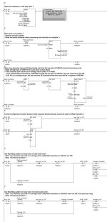
I am back to the code you generated the other day and converted to Cscape for me.... There were minor errors causing some problems.


I now have it checking for BC as the last two and responding correctly.


The problems i am having now:


When code is good, Light goes green. Cylinder stays extended (needs to retract on COMPARE_COMPLETE)


(Cylinder can extend when making PART_POS2, instead of when making PART_POS1) Then green light off and clear scanned data?

PassFail Logic 09242021B.jpg
 
I am back to the code you generated the other day and converted to Cscape for me.... There were minor errors causing some problems.

I now have it checking for BC as the last two and responding correctly.
Wow, really? Does it recover from a bad or short or long code as well? I'm chuffed about that!

The problems i am having now:

When code is good, Light goes green. Cylinder stays extended (needs to retract on COMPARE_COMPLETE)

(Cylinder can extend when making PART_POS2, instead of when making PART_POS1) Then green light off and clear scanned data?


Um, there have been a few different descriptions of the solenoid cylinder:

  • two output bits, [SOL_RET %Q1] and [SOL_EXT %Q2] to retract and extend, respectively, the cylinder?
  • one extend output bit, [SOL_EXT %Q2?], with a spring return
  • one return output bit, [SOL_RET %Q1], unknown how to extend.
I suggest the logic driven by the four bits PP_POS1, PP_POS2, Compare_Complete, and Compare_Fail, should assign a 1 or a 0 to a single, internal bit, call it Extend_cylinder, where 1 means extend and 0 means retract, and then the SOL_EXT and/or SOL_RET bits can be set from that single bit. That way, all of the circuits will be either Start/Stop or simple [NO/NC Contact => NO Coil] circuits.

E.g. Say the PP/Compare logic assigns a 1 or a 0 to Extend_cylinder. So the SOL_EXT bit, if it exists, should be 1 when

  • The logic says to extend the cylinder
  • AND
  • The cylinder is not yet extended
    • E.g. say CYL_IS_EXTENDED is an input, from a prox, that is activated - i.e. is 1 - when the cylinder is extended enough to hit the prox
So, like this:

Extend_cylinder CYL_IS_EXTENDED SOL_EXT
--------] [---------------]/[------------------( )---------
Q%2?


The logic for SOL_RET, if present, is similar:

Extend_cylinder CYL_IS_RETRACTED SOL_RET
--------]/[---------------]/[------------------( )---------
Q%1


Where CYL_IS_RETRACTED is an input, from a prox, that is activated - i.e. is 1 - when the cylinder is retracted enough to hit that prox,


N.B. If there is a spring e.g. there is no SOL_EXT, then only one of those is needed, and the remaining [NC CYL_IS_EXTENDED/_RETRACTED] contact is not needed.


N.B. Also, if we use one or both of those rungs, the [NO Coil SOL_RET] at the end of Rung 8 in OP's last post #53 will have to be removed.


Now that that is out of the way, we can say that the cylinder should be extended (i.e. Extend_cylinder should be 1) when either
1) The part is at position 1 and there is not yet a successful compare result


  • PP_POS1 is 1
  • Compare_Complete is 0
OR
2) The part is at position 1 and there is a failed compare result

  • PP_POS1 is 1
  • Compare_fail is 1
OR
3) The part is at position 2

  • PP_POS2 is 1
Note however that case (2) presumes case (1), because if Compare_Fail is 1 then Compare_Complete will be 0.

So after all that folderol, perhaps the simplest way to position the cylinder is to note that the cylinder is retracted only when there is a successful compare result, which logic this simple rung implements:

Compare_Complete Extend_cylinder
-------]/[-----------------( )-----------


and then make sure that the part arriving at position 2 clears any successful compare result, which can be done most easily by adding a [NC PP_POS2] to the Stop portion of the Start/Stop pattern for Compare_Complete:

xxx.png

N.B. that is probably redundant because the part may not trigger the prox at position 2 until after it leaves the prox at position 1.

We still need to deal with a Compare_Fail, but I don't yet know enough about the process to implement that.
 
Last edited:
I am back to the code you generated the other day and converted to Cscape for me.... There were minor errors causing some problems.


Hol' on there Baba Louie. In Post #53, you are showing the RECV reading 1 character into DATA=%R01000; that should be reading into DATA=%R1014!

There is no way code identical to that image is working.
 
I modified the [Barcode Time.csp] example that is described in the video and was delivered with Cscape, to make it suitable for this application. We will still have to add logic to

  • test the carriage return
  • test the last two characters
  • control the cylinder
but it should as-is robustly read bar codes of varying length from OP's scanner.

@Ted Z, let me know if it works.

See this link from my Github repo: https://github.com/drbitboy/PLC_Cscape_serial_read_logic/raw/master/drbitboy_barcode_time.zip; that has the program (.csp) and the PDF.

The bare PDF is here: https://github.com/drbitboy/PLC_Cscape_serial_read_logic/raw/master/drbitboy_barcode_time.pdf

N.B. there was a typo in the comment on rung 5: "c[pu" should be "copy" that should be corrected by now.
 
Last edited:
It sounds like with DR's help you may be getting there, as posted many times information is essential in getting accurate replies.
As we have seen there is a mountain of missing information.
In the future (or even on this thread), post more information on what you want to achieve in bullet points.
like this:
There are two photocells, one to trigger the barcode read, this is within the read window of the scanner, just after this is a divert cylinder, it is by default in the reject position, if a good barcode is read then this retracts to allow the product to pass the green lamp is lit to indicate a good product, when the product has passed PE02 that is located after the divert then the cylinder is de-energised back to divert & the green light goes out, if a wrong bar code is read then the cylinder is left in position to divert the product, the red light goes on until the product has left PE01.
If the barcode reads an invalid barcode then it is also diverted (maybe stop the system), again a lamp will indicate this.
Other scenarios.

Do you want to Reject on bad read code (assume not full 29 chars) or perhaps stop system.

Need to clear the buffer after a read.

In short:
A good read activate cylinder green light until passed PE02
A valid but wrong bar code red light until PE01 is clear
An invalid read, could be not enough chars within a given time, invalid data etc. here you have a number of choices, divert as in a wrong code. Stop the system, wait 3 or so re-tries then stop or flag an error.
No data received within a given time (maybe 3 retries) stop the system.
Some of the above may depend on how the reader deals with reads, maybe it tries x times & if no valid read sends an error code, maybe just not send anything.
It is easier to set out all scenario's before you start coding as it is easier to remove or modify code than to interweave extra code after the fact.
As suggested by DR, perhaps use a sequence variable
0: system waiting for read
10: a pack is on PE01, wait for data
20: no data within a given period
30: data valid Jump to 60
40: wrong code Jump to 80
50: invalid data jump to 90
60: retract cylinder, energise green light, wait for pack to pass PE02 jump to 70
70: release cylinder De-energise green light Jump back to 0
80: Energise red light wait for PE01 to clear jump back to 0
90: Do what ever you want to do i.e. same as 40 or maybe stop system. remember you need to go back to 0 at some point.

Using numbers rather than individual bits for steps makes it simpler to jump back or forth, the seq. variable can often be used on an HMI to show a text on on stage it is on (using multiple text lists based on a value in a variable).
Leave gaps i.e. 10 between the steps so if you want to add another step in-between there are spares.
Does not rely on having to remember to reset bits that have been set.
Example:

Initialise start, move 0 into in SEQ_Var
CMP Seq_Var with 0 and Part covers PE01 Move 10 to Seq_Var
CMP Seq_Var with 10 wait for data, if data then step on to 30 etc.
Here is a simple one using two seq. words, one is the task control the other is the actual control sequence, you will notice how easy it is to either move a value for any step back or forward depending on what you need to do, also the bunches of compares to enable say motors or whatever when within certain step numbers or range of numbers.
 
Here is an example of a bar code reader based on what I think you are trying to achieve.
I have assumed the following:
the barcode is 29 characters including the CR so for example:
1234567890QWERTYUIOPASDFGHBC And "CR"
You wish to test for the last 12 characters before the BC
I assume BC is on all bar codes & not a checksum but you seem to want to check it.
This uses a sequence word, I would have compacted it more but if you wish to look at it then it has been split into more rungs to make it easier to read, I have also put some big gaps between the sequence values in places so you can see there is no strict following of places, if more stages are required then these can be added.
Note I have put in timers just so that the coms has time to get the full string in, some of those timers are a little large i.e. delay before checking if we have data, reason is I'm using my PC as a simulated bar code scanner, HMI program & the IDE for programming so a little slower than a real bar code reader response, these can be trimmed to the minimum without processing certain stages of the code before at least 29-30+ characters have been read.
I have tested this & it worked flawlessly the barcode simulator program I wrote has 3 buttons on it so I can send a matched, unmatched, short or one that is too long to simulate what you may get.
 
I am still focusing on making the read and detection of 'BC␍' robust, where ␍ is the carriage return character.

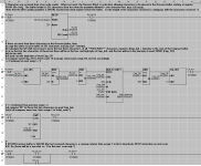
Instead of waiting for the [RX Count] of the RECV instruction to hold steady for a short time, the code below and in the Github repo* checks the last three characters in the receive buffer on every scan when the RECV instruction is active.

* drbitboy_barcode_detect_CR.csp;PDF is here.

To do this, if the RECV instruction has put more than 3 characters into the receive buffer at %R100, the code copies that entire receive buffer to %R502, which is two words offset into the compare buffer (%R500). It then byte-shifts** the entire compare buffer, starting at %R500, left by one more than the length of the characters received i.e. RECV instruction parameter [RX Count].

** N.B. byte-shift is the same as character-shift

For example, if the copied receive buffer contains only the 3 characters BC␍ with BC in %R502 and ␍ in the low byte of %R503, the 4-character (4 = 3 + 1) shift will put BC into %R500 and the ␍ into the low byte of %501.
Code:
Increasing word/byte/character address -->

    %   %   %   %   %
    R   R   R   R   R
    5   5   5   5   5
    0   0   0   0   0
    0   1   2   3   4
    L H L H L H L H L H  <== L is low byte; H is high byte
            B C ␍        <== Before shift; length = 3
    B C ␍                <== After (length+1)-character left shift
Another example: if BC␍ are the last 3 characters of 12 characters received, then B will be in the high (second) byte of %R506, and C␍ will be in %R507, and the left shift of 13 (= 12 + 1) characters will again put BC into %R500 and the ␍ into the low byte of %501.
Code:
    %   %   %   %   %   %   %   %   %
    R   R   R   R   R   R   R   R   R
    5   5   5   5   5   5   5   5   5
    0   0   0   0   0   0   0   0   0
    0   1   2   3   4   5   6   7   8
    L H L H L H L H L H L H L H L H L H
            1 2 3 4 5 6 7 8 9 B C ␍      <== Before shift; length = 12
    B C ␍                                <== After (12+1)-char left shift
So however many characters have been received, the last three will end up in %R500 plus the low byte of %R501. Once there it is straightforward to test them for the final ␍ character and the leading BC string, and react accordingly.

xxx.png

I could copy into %R501 and left-shift by one less than the length, but it does not matter; I used %R502 because originally I did not test for [RX Count] of 3 or more, and needed to ensure the shift was a positive number.
 
Last edited:

Similar Topics

Good Afternoon , I'm sure there are many Ishida Muti-Head Weigh Systems . We have a Ishida CCW-M-214W Multi-Head system . We are...
Replies
1
Views
505
Hi all, have a project which requires reading a weigh head weight over ASCII. Never really touched ascii so struggling a bit. The weigh head is in...
Replies
11
Views
1,234
Good Morning , We have a Ishida Multi-Head Scale . I had experiece with them for chips , crackers , etc. , but now we are using them for...
Replies
7
Views
452
Hello expert I have migrate legacy project that use Applicom OPC DA with 3rd client and S7-400. I see in client code add item string call...
Replies
0
Views
360
Got another one a whole team of us and the OEM cannot figure out. Powerflex525, 20HP VFD, commanded over Ethernet won't turn a motor it's turned...
Replies
32
Views
7,865
Back
Top Bottom