Help scale an RTD with a 4-20mA SIG Conditioner

skyfox

Lifetime Supporting Member
Join Date
Nov 2006
Location
CA
Posts
279
Good day all,

I am having bit of an issue getting my head around this RTD scaling issue. Be forewarned, my head has been known to be "THE" issue for quite sometime.

PHYSICAL DEVICES:

RTD - OMEGA 4 Wire -30 to 260 C PT100 RTD

Signal conditioner - OMEGA PRCTL series 2, 3, or 4 wire RTD to 4-20mA output. The signal fed to the PLC is scaled according to the signal conditioner settings (blue marking) in the chart below.

Issue:


I am about 2 degrees off with these settings. This is the closest I can get to the actual temp. Any higher or lower ranges in the signal conditioner settings skews the actual temp by more than +/- 5 Deg C.


REFERENCE:


In the same loop is a Brooks Automation precision Mass Flow controller with a built in RTD. It consistently reports around 31.5 Deg C which in fact is the correct temperature in the process loop.


Help Needed:

How do I correctly scale this RTD with this Particular signal condition to the range I need so that I am within 0.5 DEG C of the reading from the MASS FLOW CONTROLLER? I do not care about the lower range in this instance. Just the ambient inside the process loop which can never be above 32 C or below 28 C.


SIDE NOTE FYI.

Mass Flow Controller - $5,000 (Used buy one of worlds top 3 semiconductor equipment manufactures and dictated by them that we use it on this test jig.

RTD - OMEGA RTD ~$170
SIG Conditioner - OMEGA Signal Conditioner ~$230

We use OMEGA's -200 to +850C RTD's with this same signal conditioner for this very same customer and they work flawlessly,for both HI-TEMP and Cryogenic applications.

Any thought or suggestions on how to go about properly scaling this RTD with this specific signal conditioner in this particular scenario?

Many Thanks.

Cheers!
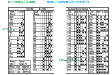
RTD SIG COND.png
 
hi, go back to basics.

Measure the resistance of the RTD, is it what your expected for the given temperature?.... Is it connected 2 wire, 3 wire? 3 wire accommodates the resistance for the length of the cables

If the RTD is 'good' measure the mA . Is the mA as expected?

If the mA is 'good' check the PLC is configured for the correct mA (0-20/4-20)

Check the PLC card at 4mA and 20mA.. is it giving you the expected raw counts? Does this agree with your scaled min/max?

This check list will lead you to the problem.
 
Edit, i see the conditioner hasnt a setting for -30 and you have set to -25 so that is an error on your 4-20mA range also
 
to conclude, your conditioner isnt set up to match the rtd (and cannot be) so you need to get an rtd to match the conditioners available scaling options
 
One is expected to configure/scale the analog input to match whatever the 4-20mA signal represents.

There is never an assumed “standard” range for 4-20mA signal. 4-20mA is understood to represent a scale or range of an analog signal , hence PLC 4-20mA inputs are ALWAYS scaled or ranged to match the range of the transmitter.

The solution in this case is not changing ranges on the transmitter or changing RTD elements. The solution is to scale the analog input channei so that it matches the range of transmitter output.
 
Have you verified which device is correct with a 3rd temperature taking device? It doesn't matter how expensive a device is, it can still have a defective part. Or are you assuming because the heating/cooling part of the process is commanded to get it to the target temp and the Brooks is reading that temp.. The brooks could be lying to you. Verify it.

IS your scale consistently off by the same amount from top to bottom, or does it skew? if totally consistent then just correct it in the PLC. You can make it work but someone can **** it right up at least with a consistent offset its easy to leave behind a note, a skew would require figuring out the ramp rate it changes by.


As said above by another.. you're going outside device compatibility. Fix that.

If the omega signal cond lets you play a little. set the input range to match the RTD capability, then set the output to whatever range you desire. I use a Define Instruments Javelin to do similar with the thermocouples we use. the thermocouple comes in the input side, I configured the Javelin to read the proper thermocouple type. then on its output I scale it to a sensible
range.. the process can't go below ambient Nor can it ever hit the top end of the thermocouple range... so I set it as 32-450 for the 4-20ma output.
 
You did not mention which 4-20mA analog Input Card you are using.

A class A pt100 is supposed to be +-0.21°C at 30°C.
A class b would be +-0.45°C. so double check your purchase order.

I couldn't find an Omega PRCTL signal conditioner. Is that the part number of the probe itself? Similarly priced conditioners from omega are advertised as "+-0.2%" accuracy, so if you are using the range -30 to 260, that's +- 0.6°C.

I have seen plc 4-20mA cards advertised as +-2% accuracy, so this would be +- 6°C. (e.g. 2080-IF2)

I guess you would sum the errors to get +- 7°C.

So step 1 is getting all your data sheets together and working out your best case scenario.

The transmitter should be set up with as small a range as possible. Even though your rtd can sense down to -30 and up to 260, you should be able to set it to say 20°C to 50°C.

Without any calibration you should set your PLC scaling Min and max to match the setting on the transmitter, not the rating of the rtd.

But it makes sense to calibrate it. Stick the rtd probe in a temperature calibrator set at the desired temperature, and then make this mA value equal to the desired temperature.

Additionally, I would not take the temperature sensor built into a mass flow meter as gospel.
 
Keep in mind I'm just a 3rd shift knuckle dragger.
It looks to me like you need dip switches 5,6, and 8 on. In your analog card set the scaling to 4ma/-200C 20ma/850C. I gather this from the box on the lower left that gives the ranges of PT100 RTD.

Bubba.
 
Setting the Range of an RTD transmitter

1. RTD element range

>We use OMEGA's -200 to +850C RTD's

I can't find an RTD with a 850°C top end, the usual high end for wire wound platinum elements is 600°C. This looks more like a spec for a thermocouple.

But assuming that the device in use is actually an RTD and not a thermocouple, the range of an RTD element describes the temperature range at which the element will provide a signal within the accuracy spec of the resistive element.

2. RTD/transmitter Circuit

The RTD is connected to the input of an RTD transmitter.

The RTD transmitter's output is 4-20mA. The transmitter's output range is scaled over some temperature range according to what makes sense for the application.

Too wide a range and the practical resolution available from the transmitter. If the temperature will be seen at outside of a certain range, why cover that range?

Too small a range will truncate the needed data.

Most transmitters will have some minimum range between the zero at 4.00mA and the span at 20.0mA.

3. Ranging the transmitter's 4-20mA output

There is no adjustment for the transmitter's input range (which is typical). The transmitter's output range is adjusted by some means, in this case, DIP switches.

4. Ranging the receiver's analog input

The receiver can be an analog input on a PLC, PAC, digital indicator, controller, recorder, DAQ.

The 4-20mA signal represents a specific temperature range. The receiver's input range MUST match (be identical to) the transmitters's output range.

A PLC's analog input range is scaled in the PLC's development software and downloaded to the PLC's CPU.

5. What output range makes sense in this application?

The perceived problem is that the transmitter's output range DIP switches does not have a -30 to 260°C range. Some other range has to be selected, and the PLC's analog input range changed to match the selected transmitter output range.


In post #1, the process temperature range is described as
>the process loop which can never be above 32 C or below 28 C.

Also, in post #1, it states
>RTD - OMEGA 4 Wire -30 to 260 C PT100 RTD

The -30 to 260°C range suggests some recommended range.

What is the source of the -30 to 260°C range?
Is -30° to 260°C the receiver's analog input range?
Is -30° to 260°C a customer specification?

It seems to me -30° to 260°C to be an overly wide range for a process that has to maintain a temperature of 28 to 32°C.

If I had to pick, I'd use 0-50°C because the process temperature range of 28 to 30°C falls near the middle of a 0-50° range, but I don't know all the process details.

The suggestion that the RTD's sensor range of -200 to +850C is not appropriate because of the stated 28 to 32°C process range; a wide range such as -200 to +850C would result in low resolution at the process operating range.
 
to conclude, your conditioner isnt set up to match the rtd (and cannot be) so you need to get an rtd to match the conditioners available scaling options


Now this is where I am a bit confused. Is the above statement really a true statement? First of all, no disrespect. I asked this purely based on my understanding that a RTD’s resistance should directly correlates to a given “ABSOLUTE” temperature.

For an example:

RTD from manufacture A = 100 Ohms at 0C
RTD from manufacture B, also = 100 Ohms at 0C. (Ignoring class A/B precision for the sake of this discussion.)

Therefore, this Ohms/Temperature relationship should hold true for all RTD’s. Grant it, some RTD’s may be spec’d for certain ranges. But they should all report the same temperature at the same resistance reading, provided their specifications happen to occupy or falls within a given temperature range, regardless of what each one’s min max range specifications are.

Again, for an example,

An RTD rated for -200C to +850C should have a resistance of 100 Ohms when temperature is 0 Deg. C as an RTD rated for -30 to +260 C. Likewise, they both should have the same ohms reading at 260 C. Then as temperature increases past 260 C the RTD rated for 260 C is no longer reliable and the other rated for +850 should continue up to 850C. Am I wrong or am I wrong on this summarization?

SPEC for the RTD is -30 C to 260 C

Since there is no exact 1:1 configuration option available with the signal conditioner, I have selected a range that is well within the specification limits of the RTD (-25 to 250) and scale the 4-20 mA signal from the conditioner to match the selected range in the PLC. Temperature reading is still off by more than 5 to 8 Deg. C. However, If I switch the RTD with a RTD that is spec’d from -200 C to 850 C and configure signal conditioner to the same range as well as the scaling in the PLC, then I am within 0.2 Deg C of the mass flow controllers. I have tried several signal conditioners as well as multiple RTD’s.
 
Have you verified which device is correct with a 3rd temperature taking device? It doesn't matter how expensive a device is, it can still have a defective part. Or are you assuming because the heating/cooling part of the process is commanded to get it to the target temp and the Brooks is reading that temp.. The brooks could be lying to you. Verify it.

There are actually three Brooks massflow controllers and the RTD is located down stream of the output path of MFC's within two inches. All MFC's report temperature within 0.1 C of each other. Brooks MFC are calibrated every six months at Brooks Automation.


As said above by another.. you're going outside device compatibility. Fix that.

Actually my range selection is well within the rated range for the RTD. Yet it is reporting an incorrect temperature.
 
Hi your correct that an RTD will give 100 ohms at 0C and they are pretty much universal

Your transmitter is set to give 4mA at -25C and 20mA at 250C therefore it wont transmit the correct 4-20mA for your desired range of -30C to 260C

Are you actually measuring from -30C to +260?
 
You did not mention which 4-20mA analog Input Card you are using.

It is a CompactLogix 1769-IF8

RTD is Class 1. OMEGA PN# RTD-3-F3105-36-T

I couldn't find an Omega PRCTL signal conditioner. Is that the part number of the probe itself?

You are correct. PRCTL was from a part number for a -200C to +850 C RTD which happens to report the temperature correctly with the range set to match and scaled accordingly in the PLC. However, this RTD cannot be used with this particular system.

SIGNAL CONDITIONER PN# OMEGA DRSL-RTD-LP


The transmitter should be set up with as small a range as possible. Even though your rtd can sense down to -30 and up to 260, you should be able to set it to say 20°C to 50°C.

I have set it to a lower range than the min max ratings of the RTD but the signal conditioner is not reporting correctly. Puzzled as to why. I have tried three different signal conditions (same make/model) with the same results.


Additionally, I would not take the temperature sensor built into a mass flow meter as gospel.

Actually there are three MFC's in the test set-up. They are calibrated every six months. They report the temperature within 0.1 Deg. C of one another.
 
Hi your correct that an RTD will give 100 ohms at 0C and they are pretty much universal

Your transmitter is set to give 4mA at -25C and 20mA at 250C therefore it wont transmit the correct 4-20mA for your desired range of -30C to 260C

Are you actually measuring from -30C to +260?

No I am not using the entire range. This RTD was specified by the customer as they run higher temperature gases thru this sub assembly. We manufacture and test this sub assembly for them but using N2 at ambient temps.

I have set the signal conditioner to -25 to +255. and the 4-20 mA signal from the conditioner is scaled in the PLC for this range and not the actual min max spec of the RTD. With this setting RTD should be reporting the correct temperature. I will try narrowing down the range say 10C to 50C and see if that would yield more desirable results.
 

Similar Topics

Hey, i'm a software engineer, and getting started in PLC programming with phoenix contact / plcnext i don't know a lot about the wiring aspect...
Replies
27
Views
4,977
Hi all, Can someone direct me int o how to calibrate my scale connected to my 1769 analog input 0 - 10 V input voltage to the card is 1.66VDC...
Replies
2
Views
1,500
I have an automated batching system that im using an analog scale to trigger automated valves to open and close. I have the programming done and...
Replies
6
Views
2,339
I have a Omega Scale controller that we just purchased. It has an Ethernet connection. It is the CNi852-C3EIT. I need to connect it to my...
Replies
6
Views
2,171
I have shot myself in the foot - per se'.... I have a customer with a scale panel that has four Rice Lake scale heads in it. I was able to...
Replies
11
Views
3,739
Back
Top Bottom