Flow PID and Level P-Only controls working together

I think once I compensate for the lost volume the oscillation will reduce greatly

No I'm also now seeing that the Effluent Flowmeter output is noisy. I am averaging it but it is potentially turbulent so I am looking at that as well. It's an old and EOL mag meter so maybe it needs to be replaced. I have a guy looking into it for me.
 
What is the timeframe and sample size (count) for the EFF_FLOW PV averaging?

Whatever it is, the PID appears to be running every scan, which is almost certainly faster than necessary; it may also be the cause of the noise. What happens if you set the Derivative parameter to 0? Since this seems to be a fairly slow-moving system, I would think 1Hz, or even slower (0.5Hz? 0.1Hz?), would be more than adequate; certainly no faster than the EFF_FLOW averaging samples.

What is the numerical range of the PID.CV values in the plot? ±10%? ±1.0%? ±0.1%?

Four decades ago I wrote a simulation for a sulfur removal plant for operator training in a refinery in Aruba; the setup had a Honeywell TDC-2000 controlling the simulated process values from a VAX/VMS system. The person installing the trainer called and said some process variable was too noisy; I could not explain why, so they added a first-order filter to the output of my simulation. Another colleague came along and re-tuned the PID controller, and the noise went away without the filter.

That may not be what is happening here, but it could be. Does the level of PV noise change if the PID control instruction is put into manual?
 
Last edited:
10 samples at 1 second intervals averaged

Yea that PID argument about running in a periodic task or continuous one has never been made clear to me. People have argued for both sides.

On new code I always use a periodic task matched to the loop time of the PID. But I have never been convincingly told that its necessary.
This one is in a continuous task as it was here before I was.
 
10 samples at 1 second intervals averaged


Is it producing one average value every second?

Or is it producing 10 moving averages every second: i.e. remove the oldest raw value from, and add the newest raw value to, a moving sum that is used to calculate an average?

Either way, having the PID in the continuous task is not necessary, although it will probably work. That also explains the values of the time-based I and D tuning parameters: they are off by a factor of a few orders of magnitude from typical values to compensate for the PID running at a different actual update times than the configured update time.
 
Yea that PID argument about running in a periodic task or continuous one has never been made clear to me. People have argued for both sides.

On new code I always use a periodic task matched to the loop time of the PID. But I have never been convincingly told that its necessary.


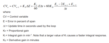
Look at the Independent Gains PID equation, which I am pretty sure you are running, at this link; that is Velocity form and you are running Positional, but that does not matter here. Run the D term of that algorithm in your head for a few scans each time PV is updated at 1Hz or 10Hz, with ∆t=2, and a scan rate of ~100Hz. Is the accumulating D term is doing anything in practice, over the course of several scans? If you think the answer is yes, then try the Positional form here, which will behave identically.

Ignore the factors of 60: the units of Ki are s**-1 and of Kd are s**1, cf. here, so they are not used in your PID.
 
Last edited:
Your units for gains are not right.
Think about it.

Why think when I can read?

xxx.png

But thinking, based on unit analysis of the independent gain equation (below), yields the same answer:

yyy.png

N.B. ignore the factors of 60, because the manual (first image, above) says seconds, not minutes, are used in the PID instruction.


Perhaps @Peter Nachtwey is referring to the implied (%CV**1 %PV**-1) units, similar to radians, in which case I agree with him, but am content to ignore them as not relevant to the current discussion, which is discovering why putting PID in continuous task without a trigger is a Bad Idea.

.
 
Last edited:
Here is a case, one of many, for ensuring PIDs run at the interval configured by their update time.

The first image below is a PID running at 2s. It uses a TON and a JSR to enforce the PID schedule within the continuous task, instead of a preferred periodic task, to make it easier to convert between this and running the PID every scan.

The entire scenario is artificial: the step change of PV is permanent because any CV change by the PID does not affect the PV; the tuning parameters are set to over-emphasize the Derivative term (Dterm); the ratios Pterm:Iterm:Dterm are 1.0:0.01:100 for the first PID execution after a step change in PV, so the CV impulse is 101.01 for one scan, after which (a) the Dterm (100) disappears, (b) the Pterm (1) holds, and (c) the Iterm accumulates at 0.01 per PID executuion.
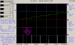
pid_characterization_00_2s_pid.png

The second image, below, is the same PID without the TON controlling the PID execution, so the PID runs on every scan of the continuous task.
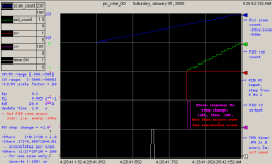
pid_characterization_01_continuous_pid.png


The key thing to notice here is that the PID CV behaves in exactly the same way, only faster: +100 Dterm; then -100 Dterm on the next scan, not 2s later; +1 Pterm holds; 0.01 Iterm accumulates per PID execution i.e. per scan. The point I am making is that the Dterm of a PID running on every scan of the continuous task will not affect a typical physical process, because it will only be in effect for only one scan of about ~20ms, which, in the case of OP's process for this thread, is not long enough to make the VFD accelerate the motor to drive the pump to change the flowrate to be sensed by the PV, before the CV drops back to 1.02, the Pterm(1.0) plus two Dterms(2*0.01), when the Dterm is reversed on the subsequent scan.

In case I have been less than clear: @Waterboy, I am certain the Derivative term of your PID is doing nothing beneficial for your process; I understand the PID works well enough so you see no reason to change it (if it ain't broke ...), and I am fine with that. However, considering that your Kd is nearly an order of magnitude and a third larger than your Kp, if it is doing anything, then it is adding noise to the process.

If anything, it is a testament to the robustness of the discrete PID algorithm that it can be made to work even when misconfigured in this way. The form of the PID equation makes it clear that, if misapplied in this way, the Ki and Kd coefficients (or Ti and Td times, in the dependent form), can be adjusted to compensate. Like the dog riding the bicycle at the circus: it's not amazing that it does it so well, it's amazing that it does it at all.
 
Last edited:
The entire scenario is artificial:

Yes! It isn't a very good simulation.


the step change of PV is permanent because any CV change by the PID does not affect the PV;

This is what is wrong with your simulation. The PV will not change in steps.


In case I have been less than clear: @Waterboy, I am certain the Derivative term of your PID is doing nothing beneficial for your process;
Probably not but not for the reasons you say. You are ignoring that the PV will not make a step jump and will increase at a rate determined by the plant parameter and the control output.
 
The PV will not change in steps.
False; see below.
Probably not but not for the reasons you say. You are ignoring that the PV will not make a step jump and will increase at a rate determined by the plant parameter and the control output.

Some day you are going to read the whole thread, smell the coffee, and speak from knowledge.

1) The PV in the current thread is the result of a 1s average of ten values. So for the Derivative term, it is a step change, and any change in CV due to the Dterm of a PID running on every scan, i.e. every 20ms, will be all but invisible in the next averaged PV, because that Dterm disappears every 20ms. Even if PV is a moving average re-calculated every 100ms, the Dterm is going to have a minimal effect at best. Anybody that says otherwise does not know how to add two and two-hundred.

1.1) Caveat: there may be some filtering of the Dterm, which could extend its effect in time, but that also attenuates its amplitude, so I doubt that matters either.

2) There is nothing wrong with my "simulation" - it is artificial to be sure, but it demonstrates unambiguously what it was intended to demonstrate i.e. the difference between (a) running a PID unconditionally in the continuous task one hundred times faster than its update time, also fifty times faster than the update time of the PV, and (b) running the PID at its 2s update time. Flow is faster than temperature of a large furnace or level of tank with a large CSA or any system with a lot of inertia/capacitance/etc., sure, but not that fast; it's not millisecond-sensitive motion, for example.
 
In what universe does the PV change in steps? Only in your poor simulations. I know you are just trying to make a point but make it good.

I have posted many simulations here. None show the actual position, temperature or PV changing in steps.


The reason why a D term will not help is because it takes 1 controller gain to place a pole. Since the integrator comes with its own pole it doesn't count. So a single pole non-integrating system only needs a additional P gain along with the integrator gain.
 
In what universe does the PV change in steps?
Seriously?

In the universe of the current thread specifically, and in the universe of PLCs in general. In what universe do digital PLCs not do everything in steps? (that's rhetorical; the answer is "none").

Transforms and poles are great, but for those continuous models to be reasonable approximations of the behavior of discrete PLCs , there are some implicit conditions regarding sampling in the PLC that must be met. PLCs were created to replace analog relay logic, and a scan time requirement has always been a fundamental specification of any PLC for any application. To be sure, as Moore's Law has improved CPU power and speed we have thought less and less about those requirements, but certainly anyone in certain domains, say, motion control f'rinstance ;), must be acutely aware of this aspect of digital modeling and control.

For those of us who have actually read the current thread ("universe"), it is apparent that those conditions re: sampling are unlikely met: the PID instruction is running the discrete form, not the differential form, of the PID equation at least five, and possibly fifty, times for every one update of the PV.

I live in the real universe; I can draw an analogy to a theoretical world nearly as well as the next person, but I try never to forget the limits of such an analogy.
 
I feel like I need a world PID tuning championships... This would be fun to watch.

I've seen some geeky statements on the 'net, but I think this is in the top three ;).

Points for (minimising) overshoot, disturbance rejection, valve wear, operator satisfaction.

Points lost for yelling at the operator, yelling at the judges, yelling at the process.

LOL. Surely yelling at the process should gain points (and yeah, don't call you Shirley).

I think an autotuner written by Peter would be among the top finishers, and some here who have a natural feel for it would be there as well.

I'm not at all experienced; the last time I messed with tuning was for an oscillating PID, when I visited my brother and suggested that he throw some switch on the pneumatic controller and it shut the system down in about two seconds. Although I did later suggest opening a bypass valve, which changed the process enough that the PID could be stable (IIRC, the threaded nut that set the repeat parameter did not have adequate range for the base process).
 

Similar Topics

Hello, I take part in commissioning of process station with lobe pump. Speed of the pump is controlled by PowerFlex 525. A customer requirement...
Replies
7
Views
5,499
Hi, I am new to PID control, wondering if anyone can help me with this. We have a flow meter goes into VHSC point io card as input, analog output...
Replies
2
Views
2,067
I have a PID loop I would like to produce a mathematical model for. I may not have paid enough attention in the Control Systems lectures a few...
Replies
1
Views
2,116
Quick question. I have a PID controller that has the following parameters Process: Flowrate (L/s) Setpoint: FlowrateSP (L/s) Output: ValvePIDOut...
Replies
2
Views
2,461
Hi guys, Need some help. Goal: Closed loop flow control of valve positioner to a flow value. Parts: I've got a K series Rotork valve with...
Replies
8
Views
4,247
Back
Top Bottom