RSLogix 500 Assign Bits of a Word

AMarks95

Member
Join Date
Jul 2018
Location
South Dakota
Posts
224
Hello,

I have 5 sensors that must be tripped in a specific order, and anything but this order is an error. The truth table looks like so:

0 0 0 0 1
0 0 0 1 1
0 0 1 1 1
0 1 1 1 1
1 1 1 1 1

I could easily hard-code this with 5 OR statements using XIO and XIC instructions for 0 and 1 respectively. However, the first thing that comes to mind is creating an integer out of the bits and checking the value. The valid values would be 1, 3, 7, 15, and 31. Any other value would show an error. Is there a way to do such a thing in RSLogix 500?
 
Start with an INT tag "target" with a value of 0.

As long as the word of sensor bits equals the target value, then do nothing (the next sensor has not triggered).

When the word of sensor bits does not equal the target value, then

  1. double the target (MUL target 2 target, or ADD target target target)
  2. add 1 to the target (ADD target 1 target)
The target value will ideally match the next expected word of sensor bits in the sequence (0 becomes 1; 1 becomes 3; 3 becomes 7; etc.).

If the word does not equal the target value, then a sensor has changed from 0 to 1, or vice versa, out of order.

When the target value reaches 31 (or 63), change the value back to 0.


But SQI is better.
 
Based on the title of your post, I'm guessing (caveat emptor) that you have sensors at I:1.0, .1, .2, etc., and you'd like to look at all 5 bits simulataneously, to see if they follow the pattern of 0, 1, 3, 7, 15, 31. Correct?

You can look at the entire I:1 word, rather than the individual bits within the word (I:1.x).
Thus, you can do something like EQU I:1 1 OTE Step1_Done. You'll probably want to seal that coil for the next step, and then break the coil with other logic. And exercise left to the reader.

However, it may be that you are using input points in the I:1 word, which would interfere with the clean 1,3,7 scheme. You need to mask out the higher bits.

This can be done with either a masked equal MEQ I:1 00011111 3, where 00011111 represents, bitwise, the bits you want to look at. In HEX notation, this will be '001F'.

Or you could make it a bit more "human-readable" and use a masked move -- MVM I:1 001F N7:0 -- to filter out the unwanted bits. Now N7:0 will have the values of 0, 1, 3, etc., and you'd use a regular EQU instruction to look tat the value.

There'll be more to what you're trying to accomplish, but this is a good first start.
 
Thanks Aardwizz. This seems like the closest to what I wanted to do. Only thing is, now I have some rather large numbers that don't follow numerical order (i.e. the first sensor is the most significant bit at location I:2/14) Any way to rearrange the bits to give me the easy decimal numbers 0-31?
 
Now you need to do the BSL, put the input word in an INT and then use the BSL to get the lowest bit to position 0, then look at the number.
You will need to clock the BSL each scan until you get the amount of Bit shifts that you need.
 
I'm always about learning new ways to do things, but this is a prime example where you could have been done already. Is learning a fancy way to do something really worth your time?
 
Any way to rearrange the bits to give me the easy decimal numbers 0-31?

Several.

If they are contiguous, then a BTD instruction will extract the 5 bits and copy their values to a new word (N7).

If they are not, then doing it the same thing hard way, contact to coil, from XIC I:1.x to N7:0.y for the 5 inputs.
 
I'm always about learning new ways to do things, but this is a prime example where you could have been done already. Is learning a fancy way to do something really worth your time?

Not to mention the next person, which may be you two months from now, is going to have to decode the algorithm. And even if it is you and not to put too fine a point on it, but if you don't know how to do this already then you may have to start from scratch.

Also note, brute force may not be as ugly as you think: detecting a bad case is only four ORed branches: [XIC I:1/N XIO I:1/M] where /M=/10 through /13, and /N=/(M+1).

That said ...

TL;DR

It sounds like you are using bits I:1/10 though I:1/14 (five contiguous bits with the MSBit at I:1/14).

If that is the case, then my "start with 0, then repeatedly (multiply by 2 and add [N])" algorithm will work if you use 1024 as N. Either use a DINT or ensure the code does not multiply an INT by 2 once bit /14 is 1 (0111-1100-0000-0000 = 0x7C00 = 31744 = 32767-1023), as that will cause an overflow.

But if you are not comfortable twiddling bits like this, and this thread's existence suggests you are not, then use brute force or SQI.
 
I'd map them to a spare integer to get them in the right order starting with bit zero (XIC -> OTE). Then I'd have a rung with 5 NEQs in series that drive an alarm bit. Simple is fast. Simple is flexible. Simple is versatile. Simple is your friend (and mine).
 
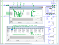
Just under a dozen instructions using SQC in a loop; the relevant code is in Rungs 0000 and 0001; the rest are for logging and generating test INTs using S:4. The first entry in the VALIDINTS INT file is ignored; I suspect that is fixable. The positions and expected sequencing of the bits is arbitrary; it would take additional logic to test whether any steps in the sequence are skipped.
xxx.png
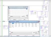
A few less instructions than that using atomic-ish instructions; again the relevant code is in Rungs 0000 and 0001.
yyy.png
 
I'd map them to a spare integer to get them in the right order starting with bit zero (XIC -> OTE). Then I'd have a rung with 5 NEQs in series that drive an alarm bit. Simple is fast. Simple is flexible. Simple is versatile. Simple is your friend (and mine).

This. Keep it simple and functional. As said, you could of been done by now.
 

Similar Topics

buen dia. tengo una falla al pasar los tags de mi plc SLC 5 0/4 a mi panel me aparece un error Problem writing value " " to item <tag name>...
Replies
1
Views
65
Will someone please convert this logic to pdf?
Replies
2
Views
118
Hello, Haven't been on in a while. I need to generate a bit level pdf of the I/O for RSLogix 500. I can generate a report but it just shows the...
Replies
1
Views
140
I would like to copy register N61:131 thru N61:147 into ST252:0 I keep failing What happens is I copy into ST252:0,1, 2 etc. What am i missing...
Replies
18
Views
556
I'm trying to fix a mess of code on an older machine that's running a Micrologix 1400 and an RS232 ASCII barcode scanner. The previous guy had...
Replies
3
Views
334
Back
Top Bottom