Scaling a zero center pressure sensor

ssarora

Member
Join Date
Sep 2021
Location
TO
Posts
2
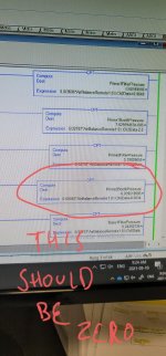
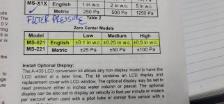
I have a zero center pressure sensor where 0.0 is 12mA, 0.5 is 20mA and -0.5 is 4mA. I cant figure out a way to get accurate results

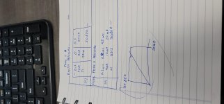
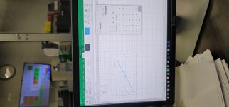
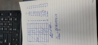
I have attached some screen shots of how I am doing it. But need more help it seems. let me know if I'm missing something.

20210910_092425.jpg 20210909_144743.jpg 20210909_144739.jpg 20210913_130938.jpg 20210913_131228.jpg
 
It might be worth grabbing one of the SCP (Scale With Parameters) AOIs from the Rockwell Sample Code Library. You would put the input minimum and maximum in raw data counts (not sure what kind of analog card you have, but could be -16383 min, +16383 max for example) and output minimum and maximum (-0.5 min and 0.5 max) and it should handle itself.
 
Easy way would be to scale from 0 to 1, then just subtract 0.5 after scaling.
 
I have yet to find a Logix5k project where the SCP Add-on wasn't well worth the Add-in.

Sometimes I think that A/B left it out on purpose to get more folks to look at the shiny new AOI concept, because every program with any amount of analog will want and need it.
 
(((Scaled Max-Scaled Min)/(Max Raw Input-Min Raw Input))*(Raw Input-Min Raw Input))+Scaled Min = Scaled Value

This is a calculation that every PLC programmer should commit to memory. At the very least, have it written down somewhere for quick reference.

As for the SCP instruction, the above calculation is essentially it. Just take that and then make your own SCP with Logix Add-On-Instruction. Function blocks and/or functions for CODESYS/TwinCAT users.
 
Summary
Use 0.000034241 instead of 0.00003 in the CPT formula.
TL;DR

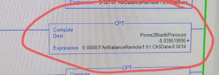
In the first image below, which calculates

  • -0.039519995 for Prime2BoothPressure
  • From the that datum, plus the supplied CPT formula, i.e.
    • 0.00003 * AirBalanceRemote1.0:I.Ch5Data - 0.5014,
  • we can back-calculate that the raw counts value of AirBalanceRemote1.0:I.Ch5Data on that scan was
    • 15396
      • i.e. = (-0.039519995 + 0.5014) / 3e-5
However, OP says that value of Prime2BoothPressure should be 0 at the analog input value of 15396, and the calculation above assumes the 0.00003 scaling factor is correct.

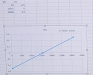
The other images from post #1 suggest a slightly different scaling factor, i.e. an independent least-squares linear fit of the data from the second image below (the eXcel linear fit) suggests the slope parameter is actually

  • 0.0000324241111 = 3.24241111e-05
and not just the

  • 0.00003
    • i.e. the "3e-05" that the eXcel chart displays. That would make the CPT formula be

  • 3.24241111e-05 * AirBalanceRemote1.0:I.Ch5Data - 5.01428070e-01
So

  • -0.50081201 = -3.24241111e-05 * 19 - 5.01428070e-01
  • 0.00163201 = -3.24241111e-05 * 15515 - 5.01428070e-01
  • 0.49918 = -3.24241111e-05 * 30860 - 5.01428070e-01
  • -0.002226 = -3.24241111e-05 * 15396 - 5.01428070e-01
So both 15515 and 15395 counts yield pressure values within two milli-whatever units the W.C. pressure Prime2BoothPressure is using.


xxx.png

yyy.png
 
This is a calculation that every PLC programmer should commit to memory. At the very least, have it written down somewhere for quick reference.

I don't want to be rude, but I have to disagree and say it is even more important than that: this is a calculation that every person on the planet should understand in their bones.

That way, they don't have to rely on memory, they can derive it from first principles.

To OP's credit, from their sketches they do appear to have the concept correct in a graphical sense, but they cannot yet translate that to numbers and a formula.

Anyone without that understanding has no sense of proportion.

;).
 
(((Scaled Max-Scaled Min)/(Max Raw Input-Min Raw Input))*(Raw Input-Min Raw Input))+Scaled Min = Scaled Value


Invaluable for sure.
One thing to be careful with is the datatypes and the theoretical range vs. real world range.


I encountered volume flow sensors that were scaled (lets say) 0..20 m3/h - 4..20mA. Some sensors could go a bit below 4mA like 3.9mA which would indicate that there is a small back flow or bad calibration, and the same at the top value 20mA with the value going slightly above to maybe 20.1.
The biggest problem i had was that i used UINT's so when the sensor was at 3.9mA my calculation would roll over to 65535~ish. Rest assured, I will not make that misstake again.


So my point is, don't use unsigned datatypes or put in protection for under/over-range.
 

Similar Topics

Hi, I have a vacuum transmitter, it's range is 30 to 0 inches of mercury. My spec calls for inches of water, no problem, use SCP to scale 0-16733...
Replies
3
Views
2,457
Hi, I have a ControlLogix system with 1756-IF16 analogue inputs. I can't scale the inputs at the card as there is a requirement to facilitate...
Replies
2
Views
39
I know nothing about simaticnet OPC server. I do know Kepware. I would only ever scale raw to engineering in the PLC, but it is possible to scale...
Replies
5
Views
212
Hi all. I'm working on a rehab and I'm trying to figure stuff out. See screenshot at the bottom. Local:5:I.Data[6] in BTD instruction is a...
Replies
6
Views
701
Hello all, First post here. Hitting a wall with finding info on this topic online, and none of my coworkers have a clue. I have a PanelView...
Replies
10
Views
1,335
Back
Top Bottom