siemens tia help

stu

Member
Join Date
Aug 2005
Location
England
Posts
783
hi i have had a mind blank on a tia and was wondering for a easy option .
i have a trigger signal that will see a mark and set a delay timer off and then trigger a out put to trigger a vision camera ?

how do you hold the triger on to the timer if the timer loses its enable it stops?
in ab you could use a tt bit but not sure in Tia

silly question i know but im sure you guys have the answer
thank stu
 
hi i have had a mind blank on a tia and was wondering for a easy option .
i have a trigger signal that will see a mark and set a delay timer off [TOF?] and then trigger a out put to trigger a vision camera ?

how do you hold the triger on to the timer if the timer loses its enable it stops?
in ab you could use a tt bit but not sure in Tia

silly question i know but im sure you guys have the answer
thank stu

OR that initial mark trigger with [.ET > t#0ms]?

requires the initial mark trigger to be longer than 1ms, of course, and then requires the timer .Q or summat else (camera trigger?) to eventually reset the timer.

[Update: found a rung (see image below) where I did that.

The rising edge of the BOOL [start_ton0] is the trigger to start the TON, assuming it is not already timing, but once the .ET starts advancing it keeps it timing, even when [start_ton0] returns to 0.

I forget what the purpose was, or why I used two timers when one would have been enough here, but this did t'job.

I am not sure if OP is using a TOF instead of a TON, and this particular application is likely more complicated than OP needs, but I would think a similar approach would work.]

xxx.png
 
Last edited:
Trigger signal - > Set bit


Setted bit is input for TON delay


When timer elapses, trigger camera and reset bit.
 
Lare thanks for that , I was thinking of a latch unlatch function but I thought. There was a timer function to may have helped?

But thank you again
 
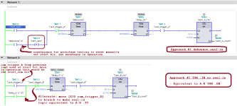
d'Oh! I forgot about the Siemens TON DB's .IN bit: it is the equivalent of the A-B TON .EN bit, and can be used as a seal-in to keep the timer going even if the "mark" start bit's value returns to 0; see second rung ("Network 2") below; this works.

The first rung ("Network 1") uses the .Q of a start bit debounce timer as the seal-in.

Notes and caveats

  • These two rungs are separate approaches to solve the query from the OP; only one or the other would be used in practice.
  • The CTUs at the ends of the rungs are proxies for the downstream vision camera in OP's process, triggered by rising edge of cam_trigger_A/_B.
  • cam_trigger_A is a one-shot,
    • by virtue of the [XIO cam_trigger_A] in the first rung,
    • so the [XIC cam_trigger A] at the start of the second rung is equivalent to a second momentary start button ("mark") that fires when the first rung triggers the "camera."
    • This was done as a convenience for testing
  • OP mentioned .TT, so A-B jargon (XIO etc.) is use here for annotation even though the platform is Siemens.
xxx.png

TL;DR

  • The process starts by manually modifying the value of [start_cam %M2.0] (OP's "mark" bit) to be 1.
  • The start_cam value was changed back to 0 by the -(R)- resetinstruction on the lower branch of the first rung when the TON [debounce %DB7] expired and debounce.Q became 1, about 100ms after the process started.
  • The [XIC debounce.Q] on that same rung also seals itself in, which then starts the second TON [delay_5s %DB6] and keeps it running until it expires.
  • The expiry of that second TON assigns a 1 to the value of cam_trigger_A, the proxy for starting the vision camera.
  • the cam_trigger_A value of 1 does two things:
    • It resets, on the next scan, the debounce and delay_5s TONs,
      • so cam_trigger_A is a one-shot i.e. 1 for one scan only,
    • AND
    • It starts the TON [delay_5.1s %DB1] on the next rung
      • This was only done as a convenience for this prototype test.
  • Once cam_trigger_A starts TON delay5.1s, the seal-in branch with [XIC delay_5.1s.IN] will maintain, after cam_trigger_A becomes 0 again one scan later, that TON until it expires.
  • The screenshot above was taken approximately 8.22s (= 100ms + 5000ms + 3s120ms) after the start_cam value became 1 to start this entire proces.
    • The first rung's two timers have run and expired in series, and its CTU (vision camera proxy) has incremented from 1 to 2,
    • and the second rung's timer is 3s120ms into its run, so that rung's CTU is still 1.
 
I think this is about as simple as it can be. This is a direct analog to using A-B .TT bit, as @janner_10 says.

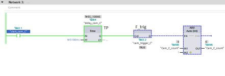
This time, an ADD instruction at the right end of the rung is the proxy for the vision camera. This is basically a State Coil/Fault Coil pattern cf. this link.

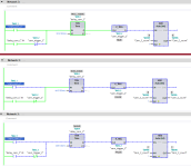
The image below is the same rung at three successive times

  • Top
    • The value of start_cam_C has been 1 continuously for at least 5.1s,
    • Which caused the ADD to increment Cam_C_count from 5 to 6.
    • The TON delay_cam_C has expired
      • So the value of delay_cam_C.Q is 1,
      • And is held there by the value (1) of start_cam_C,
      • Even though the seal-in was broken when the value of cam_trigger_C became 1
  • Middle
    • The value of start_cam_C was 0 for a time,
    • and has then been 1 for less than 3.094ms, and TON [delay_cam_C %DB4] is running, kept alive by the seal-in with [XIC delay_cam_C.IN XIO cam_trigger_C].
      • Note that, because of the way Siemens/IEC timers work, XIO delay_cam_C.Q in the seal-in will not work, because when the delay_cam_C.Q value becomes 1, that will reset the TON delay_cam_C, which will in turn assign 1 to delay_cam_C.Q, and the P_TRIG will never see that rising edge of delay_cam_C.Q.
  • Bottom
    • Following on from the middle rung (above),
    • The value start_cam_C is still 0
    • The TON delay_cam_C has has expired,
    • The rising edge of delay_cam_C.Q caused
      • Cam_C_count to increment from 6 to 7
      • and reset TON delay_cam_C.
Caveat: I am a little uncomfortable using the memory bit allocated to the P_TRIG instruction; my brother told me that is a less-than-best practice.

xxx.png
 
Last edited:
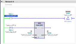
I am feeling lazy and my brain hurts from studying html, css and nore-red, so I may have completely missed the point. But, wouldn't a Pulse Timer (TP), a Falling Edge bit (N_TRIG) and a Timer Reset (RT) fit in there somewhere nicely.
 
Hmm, F_TRIG writes the result to its DB's .Q bit, and that .Q bit cannot be connected directly to the EN of the next instruction (e.g. the ADD).


So the [NO=>TP=>F_TRIG] approach will need a fourth instruction, an NO contact, to use the result assign the RLO to use. the -|N|- can convert the TP's DB's .Q bit directly to an RLO, although it does have to be on a subsequent rung.
 
Last edited:

Similar Topics

Hi I’m after some help , I have a plc program with a baumer verisens vision camera attached I have got the signals working ect but I have an...
Replies
9
Views
955
Good, Code Totalizer: IF ( Hour = 23) and ( Minute = 59) and ( Second = 59) THEN totalizerDay_previous : = totalizerDay; totalizerDay= 0; End_IF...
Replies
8
Views
1,553
Hi guys I have a 1500 cpu and a bout 5 drives on a machine on profnet And I would like to see the current and monitor online I have the plc...
Replies
4
Views
1,585
i have a question i have a string where i see a product number , but want to be able to if less then/ equals to 1 then turn off a input ? i have...
Replies
3
Views
1,745
Hi all. I'm modifying a system that's created in Tia Portal ver 14. I've changed the PLC program and added screens to the HMI sections. Regarding...
Replies
16
Views
6,137
Back
Top Bottom