RSLogix 500 - Feeling stupid

H2OTom

Member
Join Date
Jun 2017
Location
Florida
Posts
15
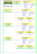
I have 3 valves that I need to open for 1 minute every 30 minutes, but not all at the same time.

I have one TON timer (Start Blowdowns Timer) running for 30 minutes and then that triggers a bit that latches and starts TOF timer. I have the first valve opening during the TOF and that works. But I can't for the life of me understand/figure out/ comprehend where I'm going wrong after that. I'd like the first valve to open for 1 minute then when it closes, open the next valve for 1 minute, then open the last valve for 1 minute. When the last valve closes, I'm going to unlatch and all 4 timers should reset. (Right now I'm running all the timers for 10 seconds for testing.

I've tried using the ".DN", ".EN", ".TT" as XIC and XIO for the previous timers with no success. I know this is probably very elementary and when I see the solution I'm going to feel even dumber than I already do. Any help would be greatly appreciated.

SCU_VALVES.PNG
 
1) This is basically a traffic light timer. I have found that, rather than having a bunch of spaghetti cascading 3 timers for 10s each, it is simpler to run one timer for 30s, and to

  • execute action 1 while .ACC is between 0 and 9,
  • execute action 2 while .ACC is between 10 and 19,
  • execute action 3 while .ACC is between 20 and 29 (or greater than 19 and .TT is 1 or .DN is 1 (TOF))
  • For that matter, you could combine all the timers in one timer that runs for 33min (=1980s)
    • do nothing for thirty minutes while .ACC is between 0 and 1799
    • open valve 1 for one minute while .ACC is between 1800 and 1859,
    • open valve 2 for one minute while .ACC is between 1860 and 1919
    • open valve 3 for one minute while .ACC is greater than 1919
2) Cascading TOFs is messy; I am not sure why

3) Aside from all that, I too am curious if your original approach will work, so, looking at your code, I have to ask where B3:0.0/0 is ever unlatched?
 
Last edited:
Also, on Rung 0004, the [XIC I:0/1] and [XIO B3/1] instructions are redundant: if either evaluates False, then T4:2/DN will be 1 from Rung 0003 and the [XIC T4:2/DN] instruction will be True on Rung 0004.
 
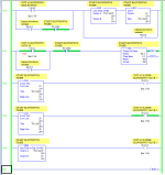
TOFs are tricky to cascade; see attached; this is more complicated than it needs to be, but it seems to works and meet OP's spec.

  • Added an ONS between each TOF's trigger and the TOF instruction itself.
  • Inverted the trigger for the first TOF
  • Changed [BLOWDOWNS INITIATED] from OTL to State Coil/Fault Coil pattern (cf. this link).
    • Third valve closing restarts cycle by assigning 0 to value of [BLOWDOWNS INITIATED B3/0]
  • Assumed
    • Repeating 10s-all-closed/10s-open-1/10s-open-2/10s-open-3 as long as [UNIT #1 BLOWDOWN AUTO SS] is 1
    • Not sure how to respond to [UNIT #1 BLOWDOWN SEMI BUTTON]
 
And finally, a single-timer solution seems simplest; first rung implements immediate blowdown when semi button momentary becomes active.

xxx.png
 
drbitboy: I like the use of Limit. I think you've mentioned using it this way somewhere else, but it wasn't apparent to me how you were using it. ...Nice. I'll write this one down for later.
 
still not ONE rung..


BST XIO T4:0/DN TON T4:0 1.0 1980 0 NXB LIM 1800 T4:0.ACC 1859 OTE O:0.0/0 NXB LIM 1860 T4:0.ACC 1919 OTE O:0.0/1 NXB LIM 1920 T4:0.ACC 1980 OTE O:0.0/2 BND
 
still not ONE rung..

BST XIO T4:0/DN TON T4:0 1.0 1980 0 NXB LIM 1800 T4:0.ACC 1859 OTE O:0.0/0 NXB LIM 1860 T4:0.ACC 1919 OTE O:0.0/1 NXB LIM 1920 T4:0.ACC 1980 OTE O:0.0/2 BND

+1 noice! I wish I'd thought of that.

The last LIM could be a GEQ or GRT.
 
Last edited:
Thanks!

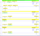
Thank you all for your help! I re-wrote it all and this is what I came up with. It appears to work quite well on the emulator. We'll see once I put it into use. Any comments or criticism is accepted! 🍻
 
General

Well done. It's working so "if it ain't broke ..." may apply, but you asked ...

Cascading timers will work, but in three months it will be difficult to parse at best, if not outright confusing at worst, when you are trying to diagnose some random sensor failure. The paucity of informative rung comments only exacerbates this problem. Cf. the post by @AutomationTechBrian.

If we stick with the cascaded timers, at a minimum the timer structures should be re-distributed, so T4:3/DN starts T4:4, T4:4/DN starts T4:5, etc.; that way it's easier to follow the sequence when are looking at it in the future.

It looks like there is now an additional 30s delay between the closing of one blowdown value and the opening of the next one. That means there will be times during a blowdown event (B3:0/0 is 1) when all three valves will be closed, so the [TON T4:2] on rung 0003 will start timing, but not reset before it expires. That should not cause any problems.

The ordering of the rungs may not matter, so although I understand the current ordering is based on the sequence in which events occur, it may be easier to parse (understand) if rungs are grouped by function. This is a style/personal preference issue, but something to think about. E.g.

  • The lower output branches on Rungs 0007/0009/0011 of [XIC T4:n/DN OTE O:0/[n-2] are the main outputs, and could be grouped by themselves at the end.
  • Similarly, Rung 0013 is functionally part of the starting and stopping of the cascading timers, so 0013 could be grouped with Rungs 0003-0006.
Specific

Rung 0001: [XIC I:0/3] is redundant; the [XIC T4:0/DN] in series with that cannot evaluate True unless I:0/3 is already 1 (cf. Rung 0000).

Rung 0002: [XIC I:0/3] is redundant here too; same logic as the previous case, but going through B3:0/2 as well.

Rung 0001: the lower output branch [XIC T4:1/DN RES T4:0] can be removed: T4:0 will already be reset on Rung 0000 when T4:1/DN becomes 1 because of the [XIO T4:1/DN] feeding the [TON T4:0]

Rungs 0000/0001/0002: B3:0/2 is redundant with O:0/0; an unconditional [OTE O:0/0] could be added as an output branch to Rung 0001, around/in-parallel-with [TON T4:1], because the input rung already has [XIC T4:0/0]; that would eliminate current rung 0002 entirely.

Rung 0003: the [XIO O:0/4] will evaluate to True in the delay times between valve 1 closing and valve 2 opening, and between valve 2 closing and valve 3 opening. [XIO B3:0] might be a better choice here.

Rungs 0005/0006: there are two counter resets, [RES C5:0], happening in two different places; I think it would be better to drop it from lower output branch of Rung 0006 and make Rung 0005 be [BST XIO I:0/1 NXB XIC B3:0 RES C5:0].

Rung 0012: [XIC B3:0/0] is redundant; none of the ORed [XIC O:0/n] branches that follow in series with can evaluate True if B3:0/0 is not already 1.

Run 0012: as noted above, with the delay times between one valve closing and the next opening, the "In Progress" output 0:0/4 will be off even though a blowdown event has started. I assume that is what is desired.

Rung 0013: [XIC T4:5/DN] is all that is needed on the input (left) side. The double [XIC T4:3/DN] instruction, one of which is probably meant to be [XIC T4:4/DN], must both evaluate to True before T4:5/DN becomes 1, so they can both be removed.

Rungs 0006/0007: B3:0/0 is redundant with T4:3/DN. So the logic driving the upper output branch [OTL B3:0/0] on Rung 0006 could be moved to be the Start portion of a Start/Stop pattern on the input feeding the [TON T4:3] on Rung 0007. An extra branch, [XIC T4:3/EN] could handle the seal-in to keep the TON alive, and then an [XIO T4:5/DN] in the middle would handle the Stop portion of the Start/Stop pattern to run the T4:3 timer, which would also allow you to eliminate current rung 0013, because the expiry of T4:5 would cascade to reset all of the timers. B3:0/0 would no longer be used anywhere. The only change in behavior would be that the program loses the Latch of B3:0 if the PLC loses power or otherwise leaves and then re-enters RUN mode; we don't know if the Latch/Unlatch of B3:0/0 is there to continue a blowdown event across a PLC mode change or not, or is just how OP chose to handle the logic.

Summary

With the exception of that last item to eliminate B3/0, I think removing redundancies, and improving the comments, will make the program easier for the next person to understand, especially if that next person is OP three months hence.
 
General

Well done. It's working so "if it ain't broke ..." may apply, but you asked ...

:geek::geek::geek:
I went though everything you listed and as I did I realized how cumbersome and overcomplicated I had made things. I greatly appreciate you taking the time to give your feedback. I'm still learning đź“š this stuff and love it.

To answer your question about the B3/0 latch; I do want the blowdown to resume if it had been in progress before a power loss or state change.

This program is going to replace some IDEC PLCs that have been in use for close to 15 years and are beginning to fail. The HMI for one already has died. The program controls the rise and fall of the sludge blanket in our super pulsator clarifiers, as well as evacuates the excess sludge by means of the blowdown valves under head pressure.

This is only the 2nd program I've written. I didn't have a program to go by as I don't have the software to read from the old IDECs. So I just used my operational knowledge of how it works and the wiring in the existing cabinet. I'll be putting one online before the end of the month. I just have to find some sort of HMI that will work. But that's another topic...
 
If you really want things to pick up where they left off on power loss or state change, you may want to try using retentive timers (RTO). One of those would work really well with drbitboy's LIM method and would pick up where it left off. With a blow down, you may want to just pick up on the same valve and get the full cycle for that valve when things come back up. If so then what you have done with multiple timers would probably work better.
 
I thought about using RTOs but I believe the way I have it setup right now will just start the blow down cycle over at valve one. I'm ok with that. I'd rather make sure the sludge was moved out of the clarifier rather than end up in my filters.
 
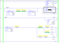
Here is an implementation of the blowdown logic with a single RTO that has been tested to save state through mode (RUN => Program => RUN) changes of the PLC.

The version shown here

  • runs 10 times faster i.e. does 60s (1minute) in 6s,
    • so T4:0.PRE should be changed to 60,
  • has an output branch on Rung 0002, which jump-starts the counter at the equivalent of 19h55m of the 20h pre-blowdown period, that can be removed,
  • has SourceB = 3 GRT on the lower input branch on rung 0001 so the inter-valve delay is half of the RTO preset,
    • should that be changed to SourceB = 30
  • has XICs and XIOs of the .ACC/n bits, which should of course be replaced by EQU instructions, but I could not resist doing it this way.
Adding the [AUTO] switch, as well as the [SEMI BUTTON] to manually initiate blowdown before the 20h expires, are left as an exercise for the user.

xxx.png
 
Last edited:

Similar Topics

Hi Everyone, I am not proficient in RSLogix 500 so I have a question regarding the evaluation of N7:0 data as an input. So as I understand in...
Replies
1
Views
75
I have a little bit of experience with Allen-Bradley. I have a Micrologix 1500 (RSLogix 500) and a PanelView Plus 7 (FactoryTalk View Studio ME)...
Replies
3
Views
159
buen dia. tengo una falla al pasar los tags de mi plc SLC 5 0/4 a mi panel me aparece un error Problem writing value " " to item <tag name>...
Replies
1
Views
81
Will someone please convert this logic to pdf?
Replies
2
Views
127
Hello, Haven't been on in a while. I need to generate a bit level pdf of the I/O for RSLogix 500. I can generate a report but it just shows the...
Replies
1
Views
155
Back
Top Bottom