cmothebean
Member
Hello,
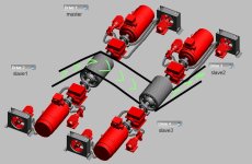
We changed from steel to fabric belt (lighter, more stretch) and are now getting quite aggressive starts on an unloaded belt and at times not getting a loaded belt away without forcing the CST clutch pressures (I have since removed the control room's ability to change the pressures). It is a ~3km belt with four CSTs. Working in RSLogix5000. I've been reading a lot of the PID themed threads on here and have gained a better understanding of what I'm working with.
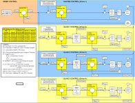
There is a SPEED PID which runs the show. The CV from this goes to the SPs (factored by load share multiplier for torque compensation) for the MASTER and SLAVE PIDs to control the CST clutch pressures. All PIDs are dependent and SP-PV.
SPEED: 0.3, 0.3, 0
MASTER: 0.18, 0.03, 0
SLAVES: 0.18, 0.3, 0
(prop gain, reset time, deriv rate)
Start sequence goes something like:
...
set pre-charge pressures (clutch pressures > 10% sys pressure)
ramp to 10% over 30s (speed > 1.2%) - PIDs kick in here
breakaway detected (wait 30s)
ramp 10% to 100% over 3mins (speed > 98%) - linear, not S-curve as the func spec specifies
running
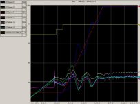
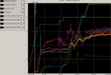
During the start sequence the CST clutch pressures are ramped up to pre-charge pressure. I should say, they are supposed to be ramped to pre-charge. They were set by an operator controlled setpoint (in %) which does not appear to have a linear relationship to the observed pressure nor do any of the CSTs have similar % si relationships. I have put some logic in to ramp them up until they're all above 10% of system pressure (as on other belts). I was considering putting some smarts in to ramp them up until an increase is seen in drive current and then backing off a little (determining pre-charge on the fly) but I haven't convinced myself it is a good idea yet. These pre-charge pressures are fed to the corresponding PID loops as the minimum output.
1) Long delay before action is seen on the CST clutch pressures.
I attribute this to the minimum output of the PID being set to the pre-charge pressure output (%). This means the CV is above the SP for most of the ramp-to-10% state so the clutch pressures do not increase. Should we be setting the output bias to this value instead of the minimum output? As the pre-charge point is our zero reference, not 0psi, correct?
2) Slaves react a long time after the Master
Master has much shorter reset time (0.03) where the slaves are set to 0.3. This is not the case in another similar belt we have on site (all are 0.18/0.003 and speed is 1.2/0.5) but when I set them all to be the same we saw lots of oscillation in the speed during startup or it didn't move at all. Should the PID parameters for these four loops be identical?
3) Tuning the thing. Not an easy task as they don't give you much time to fix things around here. Should I be dropping the integral from the master and slaves and tuning P only; adding I and tuning it; then tuning the speed PID? Could it be worthwhile adding D due to the extra stretch in this belt?
Any thoughts/ramblings appreciated.
Cheers,
Simon


We changed from steel to fabric belt (lighter, more stretch) and are now getting quite aggressive starts on an unloaded belt and at times not getting a loaded belt away without forcing the CST clutch pressures (I have since removed the control room's ability to change the pressures). It is a ~3km belt with four CSTs. Working in RSLogix5000. I've been reading a lot of the PID themed threads on here and have gained a better understanding of what I'm working with.
There is a SPEED PID which runs the show. The CV from this goes to the SPs (factored by load share multiplier for torque compensation) for the MASTER and SLAVE PIDs to control the CST clutch pressures. All PIDs are dependent and SP-PV.
SPEED: 0.3, 0.3, 0
MASTER: 0.18, 0.03, 0
SLAVES: 0.18, 0.3, 0
(prop gain, reset time, deriv rate)
Start sequence goes something like:
...
set pre-charge pressures (clutch pressures > 10% sys pressure)
ramp to 10% over 30s (speed > 1.2%) - PIDs kick in here
breakaway detected (wait 30s)
ramp 10% to 100% over 3mins (speed > 98%) - linear, not S-curve as the func spec specifies
running
During the start sequence the CST clutch pressures are ramped up to pre-charge pressure. I should say, they are supposed to be ramped to pre-charge. They were set by an operator controlled setpoint (in %) which does not appear to have a linear relationship to the observed pressure nor do any of the CSTs have similar %
1) Long delay before action is seen on the CST clutch pressures.
I attribute this to the minimum output of the PID being set to the pre-charge pressure output (%). This means the CV is above the SP for most of the ramp-to-10% state so the clutch pressures do not increase. Should we be setting the output bias to this value instead of the minimum output? As the pre-charge point is our zero reference, not 0psi, correct?
2) Slaves react a long time after the Master
Master has much shorter reset time (0.03) where the slaves are set to 0.3. This is not the case in another similar belt we have on site (all are 0.18/0.003 and speed is 1.2/0.5) but when I set them all to be the same we saw lots of oscillation in the speed during startup or it didn't move at all. Should the PID parameters for these four loops be identical?
3) Tuning the thing. Not an easy task as they don't give you much time to fix things around here. Should I be dropping the integral from the master and slaves and tuning P only; adding I and tuning it; then tuning the speed PID? Could it be worthwhile adding D due to the extra stretch in this belt?
Any thoughts/ramblings appreciated.
Cheers,
Simon


